Purpose
The purpose of this activity is to develop the workstation control program response to the Area E-Stop and establish how the workstation recovers after the safety system is reset.
We begin by establishing E-Stop Mode from the mapped Area safety-relay status. We create OP_Mode to contain the workstation operating-mode logic, establish the common mode-status bits, and use Input001 to make EStopMode directly reflect the Area E-Stop condition.
We then review the workstation's physical response to the Area E-Stop. Because the line-level safety system removes electrical power from the workstation outputs, the equipment responds as established during the power-loss review. We also confirm that the workstation does not create a separate local E-Stop condition and identify the Manual Mode requests that must not remain actionable through E-Stop Mode.
Finally, we develop the workstation's recovery from E-Stop Mode. While E-Stop Mode is active, Auto Mode is cancelled. When the Area E-Stop is reset, EStopMode clears and the workstation returns to Manual Mode, leaving the hardware in its current state until a new deliberate command is accepted.
Establish E-Stop Mode
Input001 was defined and mapped earlier by the PLC Pro to be TRUE whenever the safety relay contact at the workstation drops out. In this way, the mapping rung already converts the physical signal into the condition needed by the workstation program.
Rather than use Input001 directly throughout the workstation program, we will use it to establish the workstation's E-Stop Mode status. We create a Ladder program named OP_Mode to contain the logic that establishes and changes the workstation operating modes. Keeping this logic together gives the programmer and maintenance technician one predictable place to determine why the workstation is in E-Stop Mode, Manual Mode, or Auto Mode.
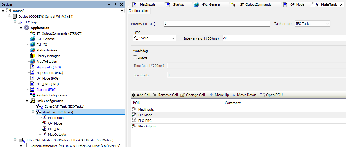
With OP_Mode created, we add it to MainTask immediately after MapInputs. This places the operating-mode logic after the current input states have been established and before the rest of the workstation control logic executes. This placement is critical, since mode changes can radically affect which commands and operations are permitted during the remainder of that same scan.
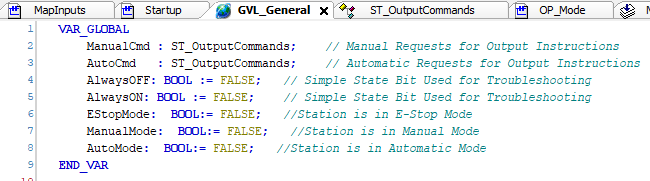
We next add three Boolean mode bits to GVL_General: EStopMode, ManualMode, and AutoMode. These globally scoped bits provide the common operating-mode status used throughout the workstation control program.
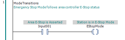
The first rung in OP_Mode establishes EStopMode directly from Input001. Because Input001 is TRUE whenever the Area safety relay indicates that E-Stop is asserted, EStopMode simply follows that mapped condition.
Review the Physical E-Stop Response
With the workstation now able to recognize E-Stop Mode, we next consider what physically happens when the Area E-Stop is asserted. The line-level safety system drops out the safety relay in the workstation cabinet, removing electrical power from the workstation outputs. This safety-system response occurs independently of the ordinary workstation control program.
Because assertion of E-Stop removes electrical power from the workstation outputs, their physical response is the same response we established during the power-loss review. The carrier stops raise, the Carrier Lift retains its selected valve state, the Carrier Lock Pin extends, and the remaining ordinary and safety outputs de-energize as previously established.
If you are joining the tutorial here, the workstation discrete output and Carrier Drive behavior, along with the reasoning behind these responses, are developed in the Develop the Power Loss Response tutorial.
The workstation does not establish a separate local E-Stop condition. E-Stop Mode simply reflects the condition of the surrounding area safety system. When the area is in E-Stop, the workstation enters E-Stop Mode and complies with that condition. When the area is not in E-Stop, the workstation operates in either Manual Mode or Auto Mode.
The control program must also ensure that Manual Mode requests which could become actionable when E-Stop Mode ends do not remain active through the E-Stop condition. This includes the retained requests identified during the power-loss review, including the carrier-stop, screw-presenter, tightening-tool, and carrier-rotation requests. We note that requirement here and will implement it as the corresponding Manual Mode control logic is developed.
Recover from E-Stop Mode
Reset of the Area E-Stop safety system is performed at the line-level control console. The workstation control program does not reset the safety system; it waits for the safety relay status monitored by Input001 to indicate that the safety-system response has been reset.
While E-Stop Mode is active, Auto Mode is cancelled and prevented from remaining active. We therefore add a rung in OP_Mode that resets AutoMode whenever EStopMode is TRUE. This ensures that resetting the Area E-Stop does not restore Auto Mode; automatic operation must be deliberately requested again.
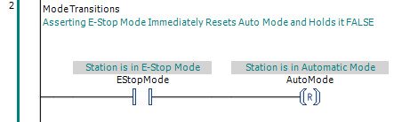
When the safety relay returns to its normal state, Input001 becomes FALSE. Because EStopMode directly follows Input001, OP_Mode then clears EStopMode during the next program scan.
With AutoMode cancelled, recovery from E-Stop Mode naturally returns the workstation to Manual Mode. We derive ManualMode directly from the other two mode states: when neither EStopMode nor AutoMode is active, ManualMode is TRUE.
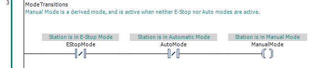
At this point, resetting the Area E-Stop returns the workstation to Manual Mode with Auto Mode cancelled. The carrier stops are raised, and the carrier remains in the position where it came to rest during the E-Stop response. As the corresponding Manual Mode control logic is developed, E-Stop Mode will be included in each command's set/reset logic so a persistent request cannot remain effective through an E-Stop condition. Until a new deliberate command is accepted, the workstation hardware will remain in its current state.