Purpose
The purpose of this activity is to develop the workstation's response to electrical power loss and restoration before the equipment control logic that depends on that response is developed.
We begin by reviewing the workstation outputs and the equipment they control. For each output, we consider what happens when electrical power is removed, what physical state the equipment assumes, and what may happen when power is restored. This review may identify opportunities to improve the power-loss response when a hardware or design change would provide more desirable behavior.
We then implement the required control-program response. We create a Startup ladder program that executes once when the application starts and use it to perform the startup actions identified during the output review before normal workstation control logic begins executing.
Review Output Behavior
Output001 controls the Carrier Feed Stop solenoid. The Carrier Feed Stop prevents an approaching carrier from entering the workstation until the workstation is ready to accept it. As originally defined in the IO Schedule, the stop is raised by energizing the solenoid and spring-returns to the LOWER position when the solenoid is de-energized.
As the PLC Pro™ examines the solenoid's power-loss response, there are some immediate concerns. If workstation output power is lost while the Carrier Feed Stop is raised to stop or hold an approaching carrier, the solenoid will de-energize and the stop will lower. The workstation could lose power while the Area PLC and transfer system remain operational, allowing a carrier to continue moving toward a workstation that no longer has the electrical power required to control it.
The preferable power-loss response is for the Carrier Feed Stop to be raised when electrical power is removed. If we reverse the pneumatic valve arrangement, the stop would spring-return to the RAISED position and the solenoid would be energized to lower it. If the stop is already raised, it remains there; if it is lowered, loss of power causes it to raise. This is normally a mechanically uneventful response and has the advantage of preventing another carrier from entering the workstation should the conveyor remain active.
If power is lost while a carrier is passing over the Carrier Feed Stop, the spring return can raise the stop beneath the carrier. This may cause a mechanical upset, but we do not expect it to create a personnel hazard or permanently damage the equipment or a carried assembly. Still, we make a note to trigger and observe this event during commissioning and verify that it is recoverable and does not present a hazard.
Notice that Output002 controls a second, essentially identical carrier stop. The Workstation Carrier Stop is also raised by energizing its solenoid and spring-returns to the LOWER position when de-energized. The same power-loss concern therefore applies to it, and there is no apparent reason for the two stops to have different de-energized behavior.
Before changing either stop, the PLC Pro reviews the proposed response with the mechanical and controls design team. The goal is to confirm that spring-returning both stops to the RAISED position is mechanically acceptable, does not create another undesirable condition, and can be implemented without conflicting with the intended operation of the transfer system. Power-loss behavior is a machine-design issue, not something the control program should decide in isolation.
The design team agrees that both carrier stops should spring-return to the RAISED position and be driven LOWER when energized. The team also agrees that a stop raising beneath a carrier is unlikely to create a hazard or cause damage. We still plan to observe the condition during commissioning.
With the proposed carrier stop changes reviewed and approved by the design team, we update the IO Schedule to reflect the revised hardware behavior. Both carrier stop solenoids now lower their respective stops when energized, with the stops spring-returning to the RAISED position when de-energized.
While updating the IO Schedule, we also correct the Output005 note to describe the Carrier Lock Pin's spring-return position as EXTENDED rather than EXTEND. This is a terminology correction; the hardware behavior remains unchanged.

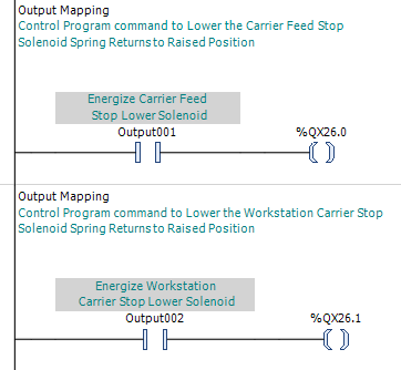
We then update the control program's MapOutputs ladder so the output mapping and rung comments agree with the revised hardware and IO Schedule. Output001 and Output002 now command their respective carrier stops to LOWER when energized.
We also consider what happens when electrical power becomes available again. If the workstation PLC loses power while a retained Manual Mode command is active, that command could still be present when the PLC restarts. Likewise, the PLC could remain powered while a failure such as a blown output-power fuse removes power from the physical outputs. In either case, restoring output power must not cause a carrier stop to lower simply because an earlier Manual command is still active.
Output003 and Output004 control the raise and lower solenoids for the Carrier Lift. These outputs operate an obverse pair on a detented pneumatic valve, so loss of electrical power removes solenoid power without changing the valve's selected position. The Carrier Lift therefore remains in its existing state through the outage, which is the desired response. No power-loss recovery action is required for this output pair.
Output005 controls the Carrier Lock Pin Retract Solenoid. When electrical power is lost, the retract solenoid de-energizes and the lock pin extends. If a carrier is properly positioned, the pin engages it; if the carrier is misaligned, the pin may contact its underside without causing damage; and if no carrier is present, the pin simply extends freely. Restoring a retained Manual retract command would only retract the pin again and does not by itself create a hazard or damaging equipment response, so no special power-loss recovery action is required.
Output006 asserts the Screw Presenter Feed Command. This command is normally associated with automatic assembly operation, although the screw presenter may also be operated manually for testing. The feed command remains asserted until the Screw Presenter has Counted a Screw input is received. If power is lost during a Manual test before that confirmation occurs, a retained Manual command could resume the feed when power is restored without another operator request. We therefore make a note to clear the Manual feed command as part of power-loss recovery.
Output007 enables the Tightening Tool, while Output008 enables reverse operation. Neither signal can cause tool motion by itself; the operator must also engage the hand trigger on the tool. Even so, if the trigger were held through a power interruption, restoring a retained Manual enable could allow the tool to operate as power returns. We therefore make a note to clear both Manual tightening-tool commands as part of power-loss recovery.
Output009 turns on the Operator Console "AUTO" pushbutton light. This output provides indication only and does not cause equipment motion. Because the light follows the workstation's actual Auto Mode status, it remains off following a power interruption and turns on again only when the workstation deliberately re-enters Auto Mode. No special power-loss recovery action is required.
Output010 provides the Barcode Reader Trigger. This output is pulsed when a barcode read is requested rather than maintained for the duration of the operation. Loss of electrical power therefore simply interrupts any trigger pulse that may be active, and restoring power does not initiate another read. No special power-loss recovery action is required.
Output011 turns on the Workstation Attention Beacon. This output provides indication only and does not cause equipment motion. Loss of electrical power turns the beacon off, and restoring power may turn it back on if the condition requesting operator attention still exists. No special power-loss recovery action is required.
The Carrier Drive also requires consideration even though it is not controlled through the workstation's discrete outputs. Loss of electrical power removes motor torque from the drive. At the same time, electrical power is removed from the Carrier Lock Pin retract solenoid, causing its spring-return valve to extend the pin. If the rotary table is positioned at a lock location, the pin locks it in place. If the carrier is rotating, the pin moves toward its extended position and introduces friction when it contacts the underside of the rotary table as the carrier coasts toward a stop.
Implementation
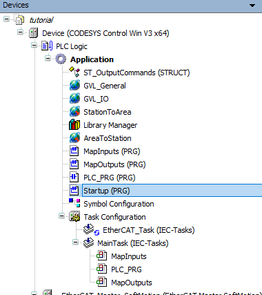
We need a ladder program (POU) to handle the required startup actions. It does not need to be scheduled. Instead, we will call it from a new first rung in MapInputs when a controlled bit is TRUE. The last action in this called program will reset that bit, so the startup ladder is called once... and only once.
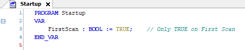
In Startup, we declare a Boolean named FirstScan and initialize it TRUE. Because FirstScan is an ordinary, non-retained variable, it returns to its initialized state whenever the PLC application starts. We will use this bit to control the call to Startup from MapInputs.
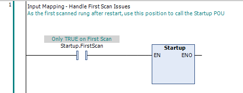
We then add a new first rung to MapInputs. Because MapInputs is the first POU in the scan order, and this is the first rung, we can use this placement to evaluate and execute any logic based on the FirstScan bit before the normal workstation logic begins executing. We use this rung to call the Startup program.
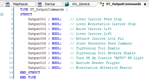
The power-recovery review has identified a need to distinguish between commands originating in Manual Mode and those originating in Auto Mode. To provide a consistent set of command bits, we create the ST_OutputCommands structure. Its members correspond directly to the workstation output names, allowing commands such as ManualCmd.Output001 and AutoCmd.Output001 to refer to the same equipment function from different command sources.
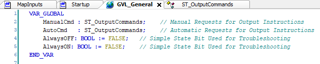
We add a new Global Variable List under the application and name it GVL_General. This provides a common location for variables that need to be available throughout the control program. In GVL_General, we then declare ManualCmd and AutoCmd as global instances of ST_OutputCommands.

We can now use the ManualCmd structure in the Startup ladder. For each Manual command identified during the output review as requiring recovery action, we add a reset instruction conditioned by FirstScan. This clears any retained Manual request before the rest of the workstation control logic can act on it.
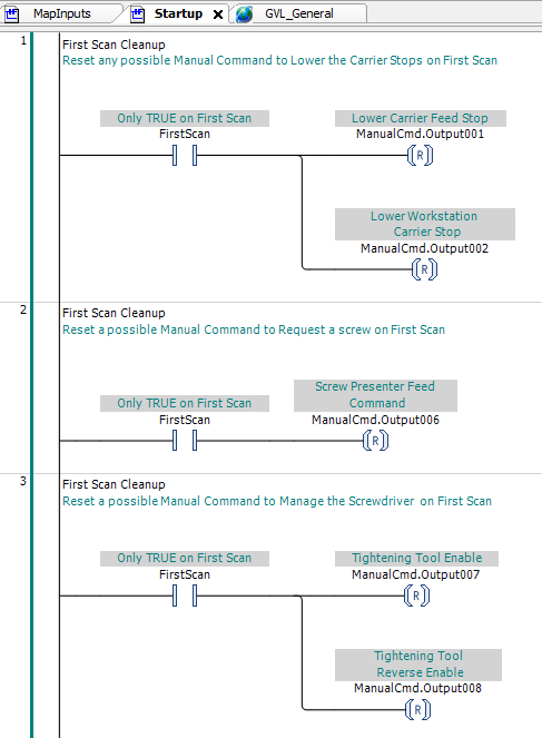
The discrete-output review identified several retained Manual Mode requests that must be cleared during Startup. The Carrier Drive is not a discrete output, but its Manual Mode rotation requests require the same consideration. A retained request must not become effective again simply because electrical power has been restored and the drive has become available.
To provide for these carrier-rotation requests as the drive control logic is developed, we add DriveRotateReq, DriveJogFWD, and DriveJogRev to ST_OutputCommands. These additions make the same carrier-rotation command names available through both the ManualCmd and AutoCmd structures as their respective control logic is developed.
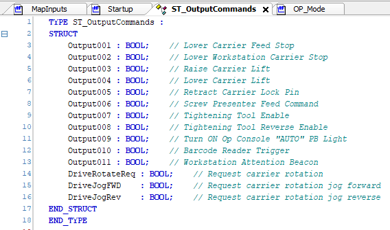
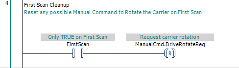
Of these three requests, only ManualCmd.DriveRotateReq could possibly remain TRUE through a power cycle. The forward and reverse jog requests require the operator to keep a finger on the corresponding button, so they do not require the same startup reset. We therefore add a separate Startup rung, conditioned by FirstScan, to reset ManualCmd.DriveRotateReq before normal workstation control logic begins executing.
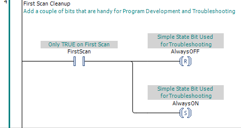
We also use Startup to establish two simple state bits used during online troubleshooting and program development. AlwaysOFF is normally FALSE, while AlwaysON is normally TRUE. We declare both globally in GVL_General so they can be used anywhere in the control program when we need to temporarily disable or enable logic while observing equipment behavior.
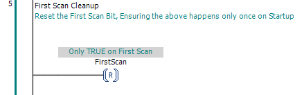
The last action in Startup resets FirstScan. Because the call to Startup in MapInputs is conditioned by this bit, clearing it prevents the Startup POU from being called again during normal cyclic operation. The startup actions therefore execute once... and only once.