Purpose
The PLC Pro develops Manual Mode to provide operators and maintenance personnel with the controls and indications needed to operate individual workstation equipment functions independently of the automatic operating cycle. These capabilities support normal equipment operation, troubleshooting, and maintenance while also providing the means to exercise and verify the equipment during development and commissioning.
We begin by reviewing how Manual Mode is established in the control program and its relationship to the other operating modes. We also establish our approach to developing individual equipment functions while recognizing that some supporting functions are needed regardless of the workstation's operating mode.
We then Prepare the HMI Interface by establishing the global variables used to exchange operator requests and equipment status information between the HMI and the control program. This provides a consistent interface as we develop the individual workstation functions.
We develop the HMI Header to provide consistent operating-mode indications and navigation controls across the workstation HMI screens. The control program supplies the operating-mode display information, ensuring that the HMI reflects the workstation's actual operating state.
We Develop the IO Status Displays to provide operators and maintenance personnel with direct access to the workstation's mapped input and output states. These displays support equipment monitoring, troubleshooting, and verification of IO operation during commissioning and maintenance.
We Develop the Alarm Display to provide operators and maintenance personnel with immediate notification of workstation alarms and warnings, along with a history of previous events. We establish the alarm classes, configuration, and HMI displays needed to support equipment operation and troubleshooting.
We Develop Modeless Functions to provide supporting capabilities needed regardless of the workstation's operating mode. These include communications monitoring, equipment status evaluation, and detection of some abnormal operating conditions. We also establish a startup grace period to prevent unnecessary diagnostic alarms while the control system initializes.
We begin programming the workstation's individual Manual Mode functions with the Carrier Feed Stop. Working through the equipment one element at a time, we develop the control logic, HMI controls, and status indications needed to operate and verify each function. We also establish the program structure for translating Manual Mode requests into physical output commands, which we use throughout the remaining equipment functions.
We next develop the Manual Mode functions for the Workstation Carrier Stop. Because this equipment operates in the same manner as the Carrier Feed Stop, we apply the same programming and HMI conventions to provide its manual controls and indications.
We develop the Manual Mode functions for the Screw Feeder, providing the operator with the controls and indications needed to operate the screw-feeding equipment independently of the automatic cycle.
The Tightening Tool requires Manual Mode controls and indications that allow the operator to exercise the tightening system independently of the automatic cycle. We also establish the logic for evaluating tightening results and identifying unacceptable torque and angle conditions.
Raising and lowering the carrier introduces additional operating and safety considerations. In the Carrier Lift section, we develop the Manual Mode controls and indications needed to operate the lift while observing the conditions that permit or prohibit its movement.
Rotating the carrier requires coordination between the servo drive, registration photoeye, mechanical locking system, and light curtain. In the Carrier Rotate Preparation section, we prepare the drive interface and develop the Manual Mode controls for operating the Carrier Lock Pin. The Homing and Normal Rotation Sequences are developed separately in subsequent tutorials.
Manual Mode
Manual Mode is not separately requested or latched. During each program scan, ManualMode is TRUE whenever both EStopMode and AutoMode are FALSE. It is therefore the workstation's operating mode whenever neither E-Stop Mode nor Auto Mode is active.
While developing the individual workstation manual functions, we will also prepare the control program and HMI with features that support BOTH manual and automatic operations. As we work through Manual Mode development, we will encounter conditions and functions that are essentially Modeless. For example, we have IO involving communications with the Area PLC and the Carrier Rotate servo drive. Loss of this communication will affect operations in both ManualMode and AutoMode. These and other mode-independent conditions will be handled as part of our Manual Mode analysis.
We develop Manual Mode by working through the workstation hardware one element at a time. For each function, we create the ladder logic and HMI controls needed for the operator to deliberately exercise the equipment, then use those controls to commission and verify the function before moving on.
Prepare the HMI Interface
As the HMI is developed, it will need both to read information from the control program and to write operator requests back to it. We prepare a common location for the PLC variables that will support this interface before beginning development of the individual workstation functions.
We add a global variable list named GVL_HMI. Variables placed in this list will provide the PLC-side interface for operator requests, status indications, and other values that need to be exchanged between the HMI and the control program.
In the installation, these PLC variables are available through the configured PLC-to-HMI communications connection. For this tutorial, we refer to that connection as PLC01. The HMI references the PLC variables through that connection while the control program continues to use them as ordinary global variables.
Establishing the actual PLC-to-HMI communications connection is specific to the PLC, HMI, network, and communications hardware used for the installation. Because this tutorial is intended to remain platform-independent at that level, we assume that the communications connection has been established and focus on the variables and program structure used across that interface.
HMI Header
The PLC Pro will design an HMI header that is included at the top of each workstation HMI screen. Repeating the same header on every page gives the HMI user a consistent place to look for high-priority information and controls that should remain available regardless of which page is being viewed. As the HMI develops, we will use this area for workstation status, navigation, and alarm indication.
The HMI needs to clearly indicate the workstation's current operating mode. We begin generating the header by creating a mode banner that clearly displays either EMERGENCY STOP MODE, MANUAL MODE, or AUTOMATIC MODE from the actual mode status established in the OP_Mode ladder.
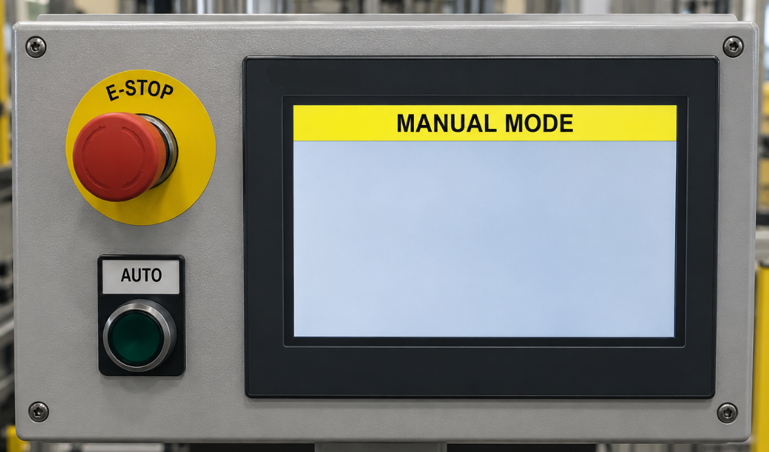
The banner should always indicate the workstation's current operating mode. This will give the operator and maintenance technician an immediate indication of the operating mode under which the workstation control logic is executing.
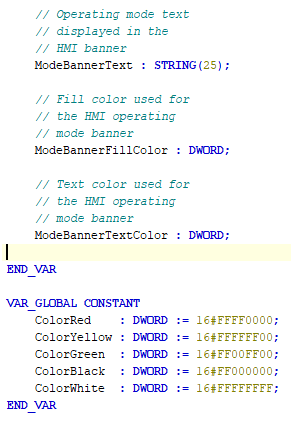
Because this banner will change state with the control program's mode of operation, we need to develop logic that provides the text and color values used by the HMI banner. Rather than requiring the HMI to interpret the workstation mode, the PLC will provide the completed display values from OP_Mode. To make the color assignments readable in the program, we first add named color constants to GVL_HMI.
CODESYS allows global values to be declared as constants by placing them in a VAR_GLOBAL CONSTANT declaration. A constant is assigned a value when it is declared, and that value cannot be changed by the running control program. This works well for color definitions because it allows the PLC Pro to give a meaningful name, such as ColorRed, to an otherwise inscrutable hexadecimal color value such as 16#FFFF0000.
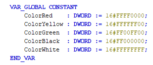
With the color constants defined, we next create the three values the HMI will read for the operating-mode banner: its text, fill color, and text color. Because these values must be available outside OP_Mode, we declare them as global variables in GVL_HMI rather than as local variables within the program.
With the banner variables and color constants available, we can now develop the corresponding logic in OP_Mode. Separate rungs establish the banner text, fill color, and text color for each operating mode. The first two handle E-Stop Mode and Manual Mode.
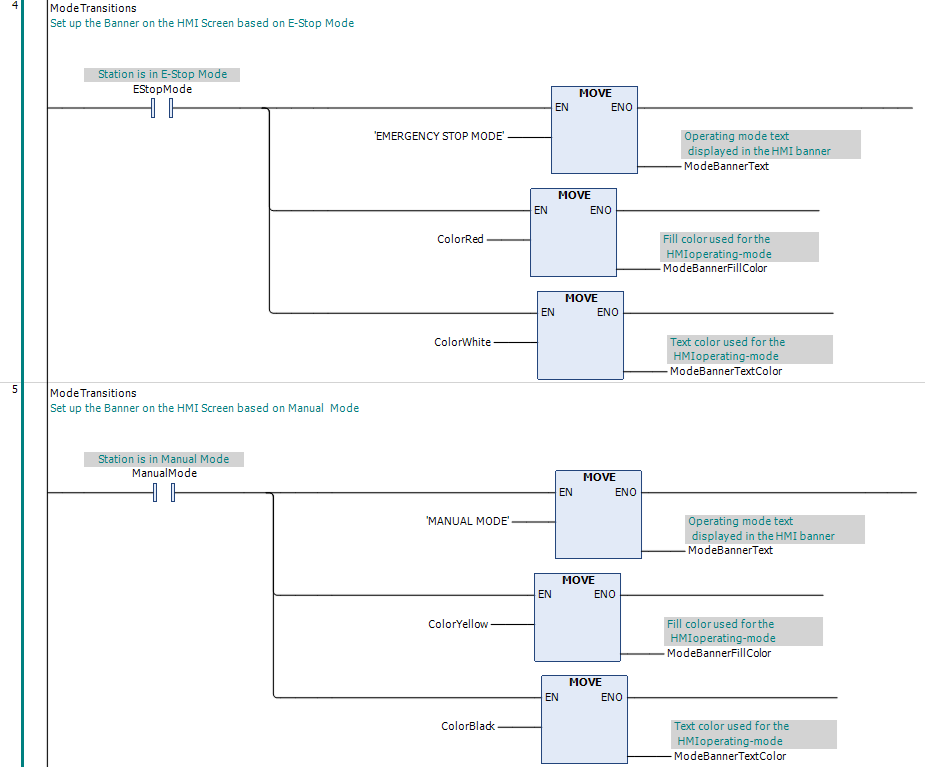
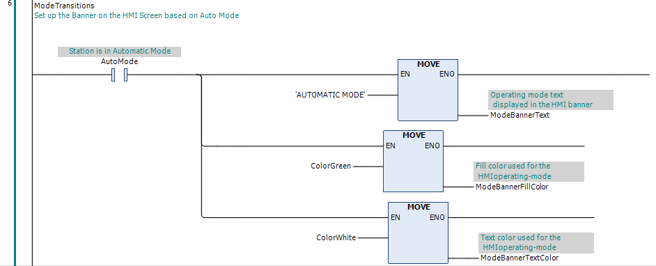
The final operating-mode banner display is AUTOMATIC MODE. We add one more rung in OP_Mode using the same pattern, providing the HMI with the text and colors to display whenever AutoMode is TRUE.
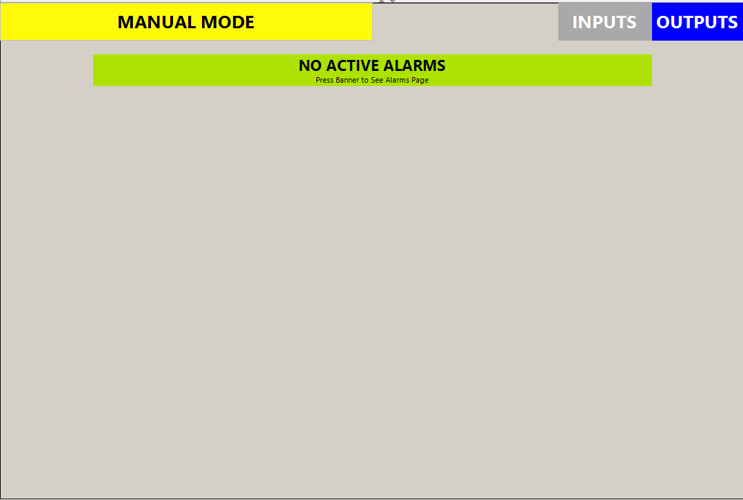
With the banner logic established in the control program, we can now view one of the completed banner states. In Manual Mode, the HMI displays the yellow fill and black text specified by the corresponding OP_Mode logic.
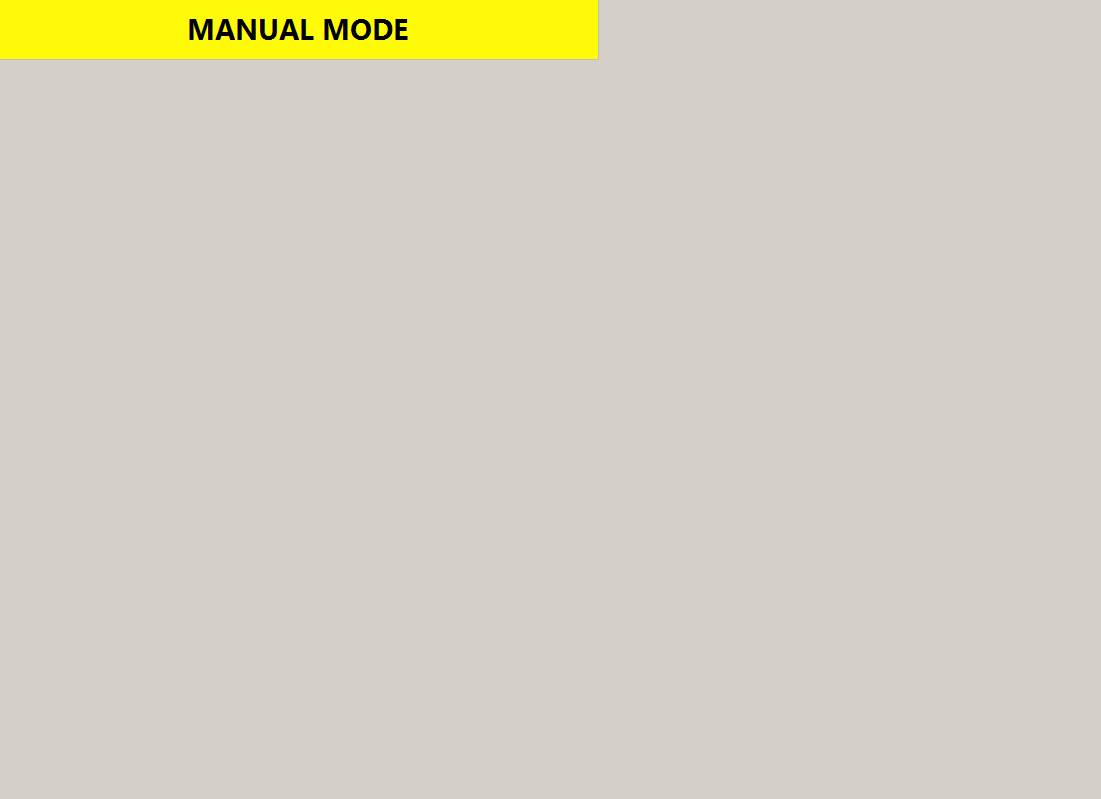
With the operating-mode logic and HMI indication in place, we have established the operating-mode portion of the common HMI header. OP_Mode now provides the completed display values that will be used on each workstation HMI screen.
Develop the IO Status Displays
Another recommended step before developing the individual workstation functions is to create HMI pages for observing the workstation IO. These displays will give the PLC Pro and maintenance technician a direct view of the mapped input and output states while the equipment is being operated, tested, and troubleshot.
The HMI obtains the workstation IO states through the PLC-to-HMI communications interface. Either the physical IO addresses or the mapped PLC variables could be made available to the HMI, but we use the mapped variables here. This keeps the HMI aligned with the same descriptive IO names used by the control program and avoids unnecessarily tying the display to the physical IO addressing.
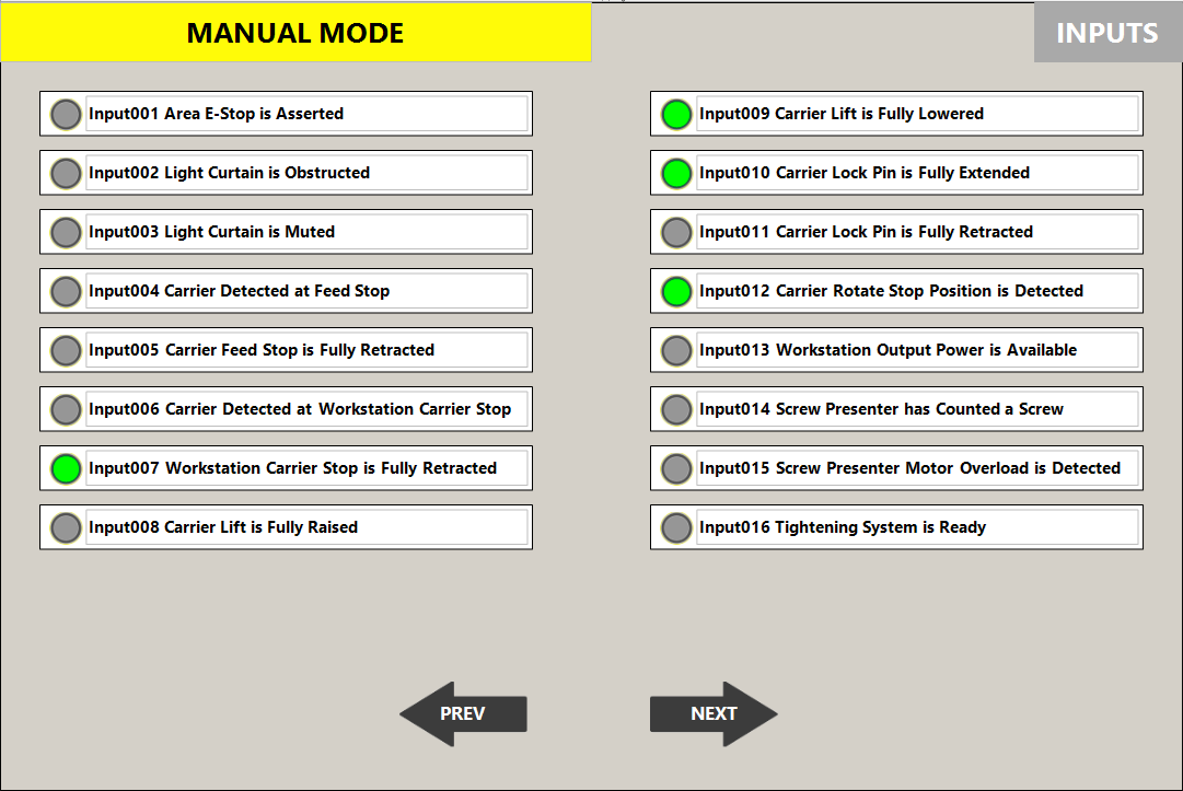
As new HMI screens are added, we also add a navigation button for that screen to the HMI header. Including these controls in the header gives the HMI user a consistent way to reach the IO status displays from the other workstation screens. Navigation buttons for each screen will have a characteristic color. The navigation button for the currently displayed screen will be greyed out.
We begin with the mapped discrete inputs. The workstation has 48 physical input points, so the display is organized into multiple pages. The first page shows Input001 through Input016 in two columns of eight. Each input is identified by its mapped variable name and description, with a status lamp showing dark gray when the input is FALSE and light green when it is TRUE.
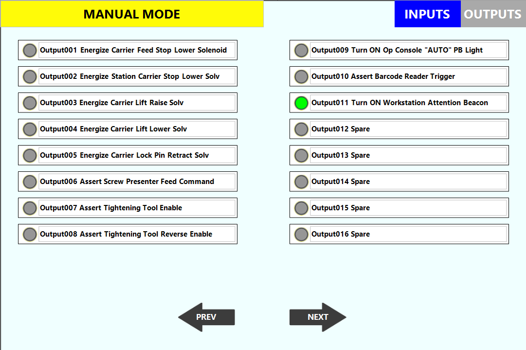
We use the same approach for the mapped discrete outputs. The workstation has 32 physical output points, so the display is organized into two pages. The first page shows Output001 through Output016, with each output identified by its mapped variable name and description. The status lamp is dark gray when the output is FALSE and light green when it is TRUE.
Develop the Alarm Display
Both in development and use, alarms and warnings will be key indicators when something goes awry. It is advisable to give these messages both an immediate presentation when active, and a way to display their history.
We begin by adding a current-alarm banner to the HMI header. This gives operators and maintenance technicians a consistent, eye-catching place to find and respond to an alarm or warning in real time.
The current-alarm banner is placed below the operating-mode banner and navigation controls within the HMI header. We will set it up to display the latest active alarm or warning message, and program it so that touching the banner opens the dedicated ALARMS screen, where the history of alarms and warnings is displayed (see below).
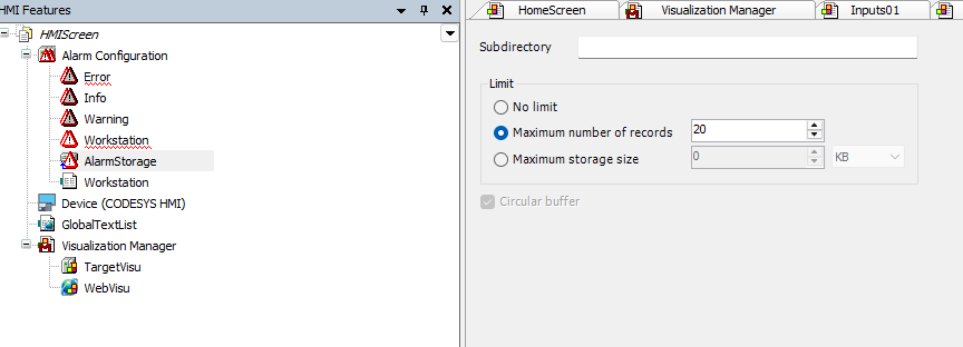
An alarm remains active while its defining condition exists, then clears when that condition returns to normal. We therefore need an archive for the alarm history, and a page to display the last few alarms (we will set this to 20).
We begin the alarm configuration by adding a Workstation alarm group. This group will contain the alarm conditions associated with the workstation and provide a common place to define the alarm condition, message, and alarm class for each condition we identify.

We next configure AlarmStorage and set the alarm archive count to 20. This provides the retained alarm records needed for the ALARMS screen and matches the number of recent alarms we chose to make available for review.
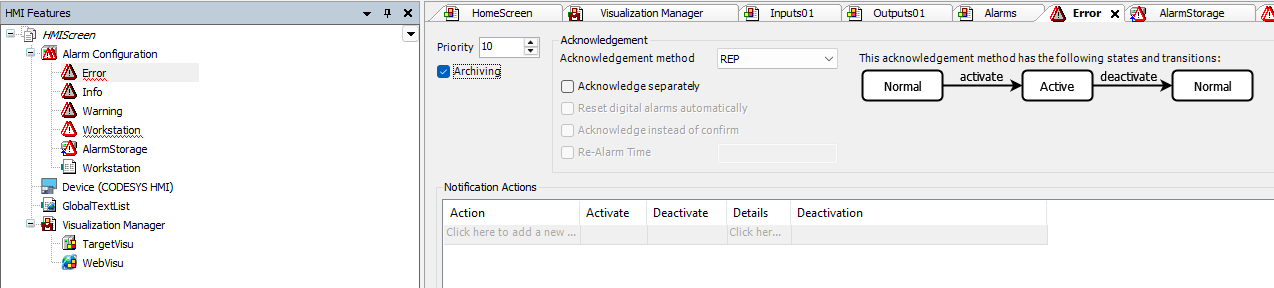
We configure the Error alarm class with Archiving enabled and set its acknowledgement method to REP. With this method, an Error becomes active when its defining condition is present and returns to normal when that condition clears. No operator acknowledgement is required, while archiving preserves the event in the alarm history after it has cleared.
Later in the workstation development, we will use the station beacon to draw attention whenever an Error or Warning is active. Because the beacon provides the attention-getting indication while the condition exists, requiring the operator to separately acknowledge the alarm would add no useful function. Archiving preserves the event after the condition clears.
We configure the Warning alarm class the same way, with Archiving enabled and the acknowledgement method set to REP. A Warning therefore remains active only while its defining condition exists, then clears automatically while its occurrence is retained in the alarm history.
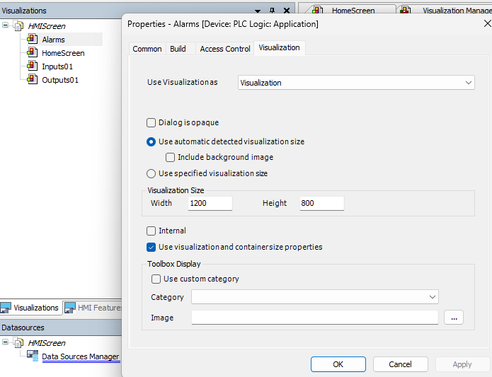
We next add a dedicated ALARMS visualization and configure it to use the same 1200 × 800 display area as the other workstation HMI screens. This provides the page opened from the current-alarm banner and gives us a dedicated place to display the archived alarm records.
We then add an alarm table to the ALARMS visualization and configure it to display the Workstation alarm history. The table shows when each alarm became active, its message, when the condition returned to normal, and its alarm class. We configure the table to provide the operator and maintenance technician with the 20 most recent workstation alarm events.
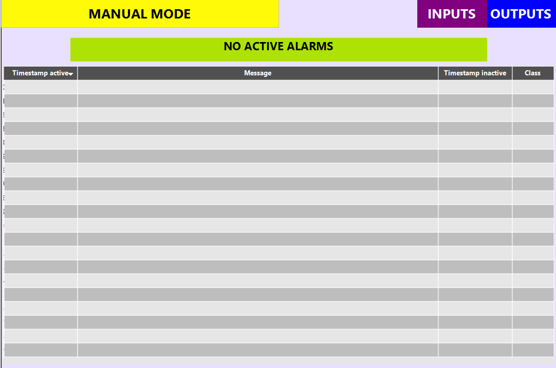
With the alarm group, archive, alarm classes, and ALARMS display established, the basic alarm system is complete. As additional Error and Warning conditions are identified during workstation development, we simply add their alarm definitions to the Workstation alarm group and assign each one to the appropriate alarm class.
Develop Modeless Functions
With the common HMI features established, we next develop several supporting control-program functions that are needed in both Manual Mode and Auto Mode. These modeless functions provide information and services needed throughout the control program. Additional modeless functions will be developed as we encounter them while working through the individual workstation functions.
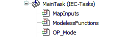
We begin by adding a Ladder program named ModelessFunctions to MainTask, immediately following MapInputs.
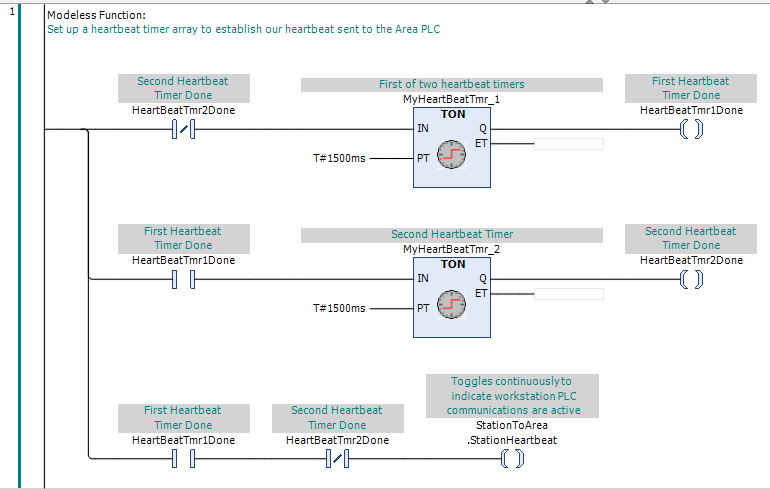
Our first modeless function generates the heartbeat sent to the Area Controller. We use the previously defined StationToArea.StationHeartbeat network variable to transmit a continuously changing BOOL value that the Area Controller can monitor to verify that our workstation control program is running.
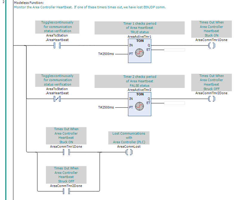
We next develop logic to monitor the heartbeat received from the Area Controller through AreaToStation.AreaHeartbeat. This heartbeat is expected to alternate between TRUE and FALSE approximately every 1.5 seconds. If it stops changing, we need to recognize that communications with the Area Controller may have been lost. We declare AreaCommLost as a BOOL in GVL_General to indicate this condition.
When the PLC application starts, communications with the Area Controller may not yet be established, leaving its heartbeat unchanged until communications become operational. Other workstation interfaces may also pass through temporary non-operational states while the PLC application and connected devices initialize.
To head off what might be a rash of non-actionable alarms, we establish a short startup grace period during which selected diagnostic alarms are suppressed. Normal PLC scans, equipment monitoring, and operating permissives will remain active throughout this period.
We do this by declaring GracePeriodOVER in GVL_General and inserting a new first rung in ModelessFunctions.
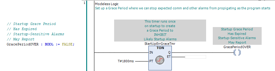
Since the timer input is unconditional, the timer will only time once, setting the GracePeriodOVER bit when done. This bit then remains TRUE for as long as the PLC continues scanning. We can then use this bit to qualify selected diagnostic alarms, beginning with the Area Controller communications loss as detected above.
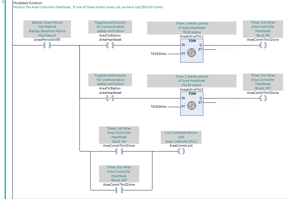
We then add an Error alarm to the existing Workstation alarm group for the AreaCommLost condition. This alarm becomes active when AreaCommLost is TRUE and clears automatically when communications are restored. The event is retained in the alarm history for troubleshooting purposes.

We next establish the availability of the Carrier Rotate Drive's EtherCAT interface. An unavailable interface does not necessarily indicate a communication failure. CODESYS provides the interface status through CarrierRotateDrive.wState, with a value of 8 indicating that the drive is in the Operational state and available for normal EtherCAT data exchange. We declare CarrierDriveCommOK in GVL_HMI to indicate whether the drive interface is operational.
Next, we establish CarrierDriveCommOK in ModelessFunctions. CODESYS automatically creates a function-block instance for each EtherCAT slave. Our CarrierRotateDrive instance uses the ETCSlave_Diag function block, which must be executed to update its wState output. Only then can we use an EQ (Equal) comparison instruction to determine whether CarrierDriveCommOK is TRUE.
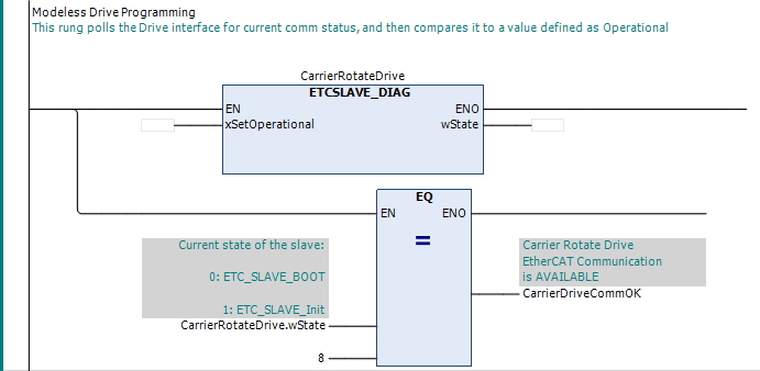
We then add an Error alarm to the Workstation alarm group with the message "CARRIER DRIVE COMM INTERFACE NOT OPERATIONAL". Since CarrierDriveCommOK is FALSE when the interface is unavailable, we qualify the alarm activation with GracePeriodOVER rather than modifying the status bit itself. This prevents the alarm from activating during the startup grace period while preserving the actual drive communications status. The alarm clears when CarrierDriveCommOK returns to TRUE.

The next modeless function detects an unexpected loss of workstation output power. Input013 indicates whether output power is available. Because the safety system intentionally removes output power during E-Stop Mode, we only assert OutputPwrLost when output power is unavailable outside E-Stop Mode. This condition activates the corresponding HMI alarm.
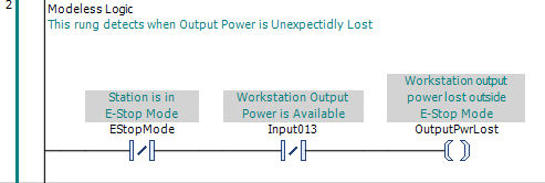
We add the corresponding output-power-loss alarm to the Workstation alarm group.

Our next modeless function establishes whether the workstation light curtain is INTACT. During our investigation of the light-curtain interface, we discover that Input002 is incorrectly described in the IO schedule as Light Curtain Is Obstructed. The actual signal indicates that the protective field is clear, precisely the opposite of its description. We correct the IO schedule description as shown below:

We make the same description correction for Input002 in the control program. The input assignment remains unchanged. Input003 continues to indicate that the light curtain is muted. We declare LightCurtainIntact as a BOOL in GVL_General and establish its state with a rung in ModelessFunctions.
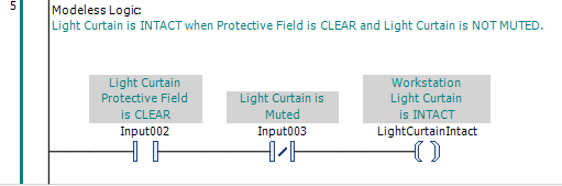
During normal carrier transfer, the light curtain may be obstructed while muting is active. This is an expected operating condition. However, an obstruction while muting is not active causes the safety system to interrupt carrier rotation and prevent lift movement. We declare LightCurtainBreach as a BOOL in GVL_HMI and establish its state in ModelessFunctions to recognize this condition.
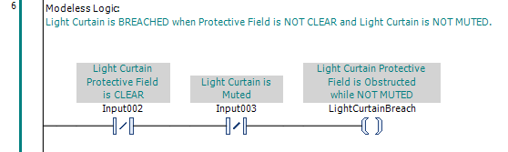
We then add an Error alarm to the Workstation alarm group for the LightCurtainBreach condition. This alarm becomes active when LightCurtainBreach is TRUE and clears automatically when the condition returns to FALSE. The event is retained in the alarm history for troubleshooting.

This concludes our initial development of modeless functions. As we work through the individual workstation hardware functions, we will encounter additional modeless requirements and develop the corresponding logic as needed.
Carrier Feed Stop
The first workstation function we develop in Manual Mode is the Carrier Feed Stop. We begin by reviewing how the assembly is actuated and what information is available to the control program, then develop the Manual Mode controls and indications needed to operate and verify it.
The operator will need commands to raise and lower the Carrier Feed Stop. Because the pneumatic valve is spring-returned, we energize the solenoid to lower it, and raise it by turning off that command.
The PLC Pro will also provide indications for a carrier detected at the feed stop, the current status of the output commanding the stop lowering action, and Carrier Feed Stop fully retracted status.
To begin implementing the ideas above, we first add a page to the HMI named "Manual". Next we use the properties dialog to set the screen size to 1200 x 800, as with each prior page. This will be the base HMI screen used for operating the equipment functions in Manual Mode.
We then add the existing header by grouping, copying, and pasting it from the Home screen. This gives us the mode announcement, alarm announcement, and navigation buttons already established for the workstation HMI.
Next, we add a "MANUAL" navigation button to the header, and copy it to the headers on all other screens. We continue with the convention that the page button for the page in view is greyed out. This gives the operator easy navigation between categories of screens.

With the Manual screen established, we can now add the controls and indications needed to operate and verify the Carrier Feed Stop. We begin with the operator controls for raising and lowering the stop.
We add two pushbuttons to the Manual screen for the Carrier Feed Stop: "RAISE" and "LOWER". These provide separate, deliberate operator commands for each requested action.
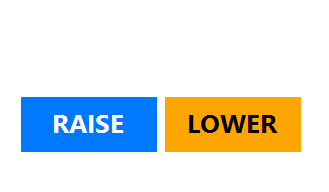
We configure each pushbutton using the CODESYS Tap function. A Tap variable is TRUE while the operator is pressing the button and returns to FALSE when the button is released. This gives us the momentary action expected from a Manual Mode pushbutton without requiring separate press and release actions.
Before assigning variables to the HMI buttons, we add two BOOL variables to the previously established GVL_HMI global variable list: CarrierFeedStopRaiseReq and CarrierFeedStopLowerReq. These variables will carry the operator's raise and lower requests from the HMI into the control program.
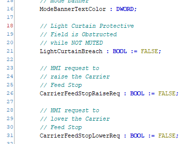
The "RAISE" button taps PLC01.CarrierFeedStopRaiseReq, while the "LOWER" button taps PLC01.CarrierFeedStopLowerReq. These variables represent operator requests rather than equipment commands or status. The ManualMode logic will use the requests to determine what command should be applied to the Carrier Feed Stop.
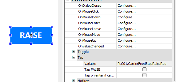
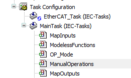
The default Ladder program PLC_PRG has not yet been used for workstation logic, so we repurpose it for Manual Mode development. We first remove PLC_PRG from the MainTask program call list, rename the POU to ManualOperations, and then add ManualOperations back to the task so it will execute as part of the normal cyclic scan.
We then place ManualOperations immediately after OP_Mode in the MainTask program call list. This preserves the execution order already established for MapInputs, ModelessFunctions, and OP_Mode. The Manual Mode logic therefore executes with the current mapped input states and operating mode already established for that scan. Its commands are available to the output-handling logic later in the same scan.
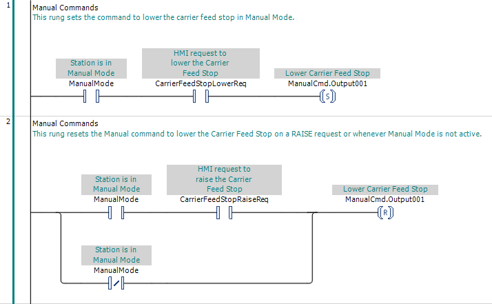
With the HMI requests available and ManualOperations executing in the proper scan position, we can now program the Carrier Feed Stop Manual Mode logic. We first create a rung that sets the Lower Carrier Feed Stop output when the HMI request to lower the stop is asserted in ManualMode.
We then create a rung that resets the Manual command to lower the Carrier Feed Stop when the operator requests RAISE in ManualMode. We also reset this command whenever ManualMode is FALSE, preventing a previously latched Manual command from becoming effective when the workstation returns to Manual Mode.
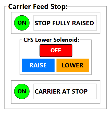
We next group the "RAISE" and "LOWER" buttons with the indications associated with the Carrier Feed Stop. We place the complete set inside a common Carrier Feed Stop group so the operator can see the stop position, lower-solenoid status, carrier presence, and the controls for operating the stop in a single equipment-function view.
With the Manual command for the Carrier Feed Stop established, we still need to link that command to the mapped output used by MapOutputs. We therefore add logic that uses ManualCmd.Output001 to assert Output001, which is then transferred by the existing output-mapping logic to the physical output.
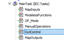
We first add a new Ladder POU named OutControl. This POU will contain the logic that links the equipment command bits to the mapped output variables, determining when each mapped output bit is turned on or off before MapOutputs transfers that state to the corresponding physical output. We then place this ladder in the scan order just prior to running MapOutputs.
We then add the output-control rung needed to complete the Carrier Feed Stop. ManualCmd.Output001 controls the mapped Output001 bit, providing the final link between the Manual Mode command and the physical output already handled by MapOutputs.
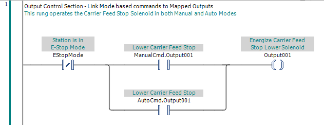
We include both Manual and Automatic command paths in OutControl from the outset. The logic generating these commands is responsible for qualifying them according to the workstation's operating mode. Our Manual command is already reset whenever ManualMode is FALSE. We will apply the same approach to the Automatic command when developing Auto Mode. This convention will be followed as we develop the remaining workstation functions.
A fundamental PLC Pro rule is that mapped outputs are never latched. Every mapped output in OutControl is driven by an ordinary output coil, never a SET or RESET coil. Internal command bits may be latched when appropriate, but the resulting mapped output state is determined on every program scan from the current commands and conditions.
At this point, the Carrier Feed Stop has both the PLC logic and HMI interface needed for Manual Mode operation. The operator can raise and lower the stop, while the HMI shows the lower-solenoid command, fully raised status, and whether a carrier is present at the stop.
We then exercise the Carrier Feed Stop from the HMI and observe its operation. The stop raises and lowers as expected, the indications follow the equipment correctly, and we find no unexpected behavior that requires additional programming or adjustment.
Workstation Carrier Stop
The next workstation function we develop in Manual Mode is the Workstation Carrier Stop. As with the Carrier Feed Stop, we begin by reviewing how the stop is actuated and what information is available to the control program.
Our review shows that the Workstation Carrier Stop operates in the same way as the Carrier Feed Stop. It is spring-return raised and is driven to the lowered position by energizing its solenoid, so we can use the same approach to controlling this stop in Manual Mode.
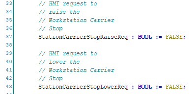
We first add two more request variables to GVL_HMI for the Workstation Carrier Stop: StationCarrierStopRaiseReq and StationCarrierStopLowerReq. These provide the HMI requests for raising and lowering the stop.
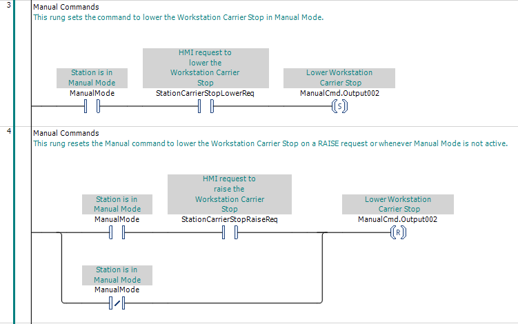
We next add the Workstation Carrier Stop raise and lower rungs to ManualOperations. Because the stop operates the same way as the Carrier Feed Stop, we use the same logic with the Workstation Carrier Stop HMI requests and output.
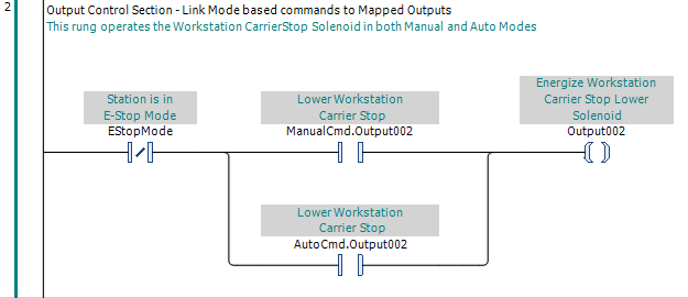
We then add the output-control rung for the Workstation Carrier Stop to OutControl.
We then add a second control group to the Manual screen for the Workstation Carrier Stop. Because it operates the same way as the Carrier Feed Stop, we use the same arrangement of raise and lower controls and operating-status indications.
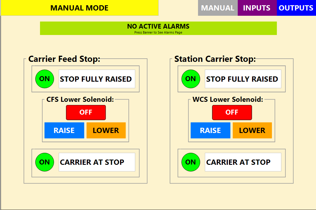
We then operate the Workstation Carrier Stop from the HMI and verify its response. The stop moves correctly in both directions, the HMI indications agree with the observed equipment state, and no unexpected behavior is found during the test.
We now have both carrier stops programmed for Manual Mode, with the HMI controls and indications needed to operate and monitor each stop. Because the two functions operate identically, we were able to apply the same programming and HMI approach to both.
Screw Feeder
The next workstation function we develop in Manual Mode is the Screw Feeder. We begin by reviewing how the feeder operates and what information is available to the control program.
From our review of the available I/O, we determine that Manual Mode operation of the Screw Feeder requires one command and two status indications. Output006 asserts the Screw Presenter Feed command, Input014 indicates that the presenter has counted a screw, and Input015 indicates that a Screw Presenter motor overload has been detected. These are the points we will use to operate and monitor the Screw Feeder from the HMI.
Alarm conditions associated with the Screw Feeder will include a motor-overload indication and a failure to feed a screw on request.
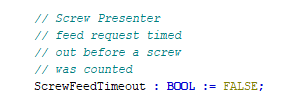
We define a feed failure as an asserted feed request where a screw is not counted within the expected time. We will need a global BOOL, ScrewFeedTimeout, to record that failed feed attempt and provide the condition for the HMI alarm. We add this new variable to the GVL_General list.
We then add the two new alarms to the Workstation alarm list.

The Screw Feeder needs its own Manual Mode controls and indications, but we do not want to continue adding equipment functions to the first Manual screen. Instead, we add a "SCREW FEEDER" navigation button at the bottom of that screen and use it to open a separate Manual Mode screen for the Screw Feeder.
We create a new visualization named ScrewFeeder and establish it in the same way as the other workstation HMI screens. We add the common header with the operating-mode announcement, alarm announcement, and screen navigation, then add the "SCREW FEEDER" navigation button to identify and access this Manual Mode equipment screen.
We create a new visualization named ScrewFeeder and establish it in the same way as the other workstation HMI screens. We add the common header with the operating-mode announcement, alarm announcement, and screen navigation. At the bottom of the new screen, we add a "CARRIER STOPS" navigation button to return to the first Manual screen and a "SCREW FEEDER" button to identify the current screen. As with our other navigation buttons, the button identifying the current screen is disabled.
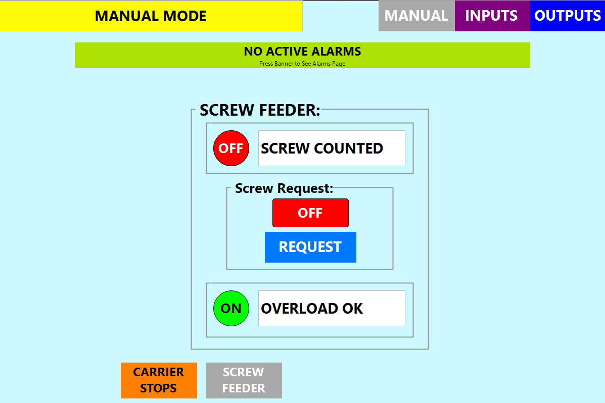
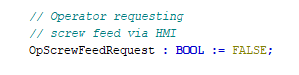
We next define a global BOOL, OpScrewFeedRequest, to carry the operator's feed request from the HMI into the control program. We add this variable to the GVL_HMI list:
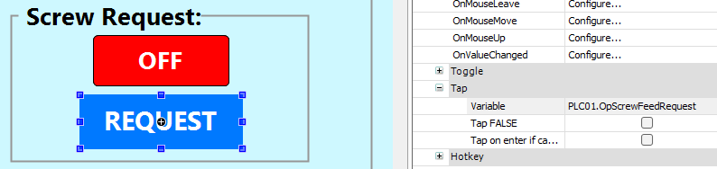
We then configure the "REQUEST" pushbutton to tap PLC01.OpScrewFeedRequest, providing the operator request that will be used by the Screw Feeder Manual Mode logic.
We also link the remaining Screw Feeder indications directly to the available I/O. The feed-command indication uses PLC01.Output006, the "SCREW COUNTED" indication uses PLC01.Input014, and the "OVERLOAD OK" indication uses PLC01.Input015, with the indication arranged to show the normal condition when the overload input is FALSE.
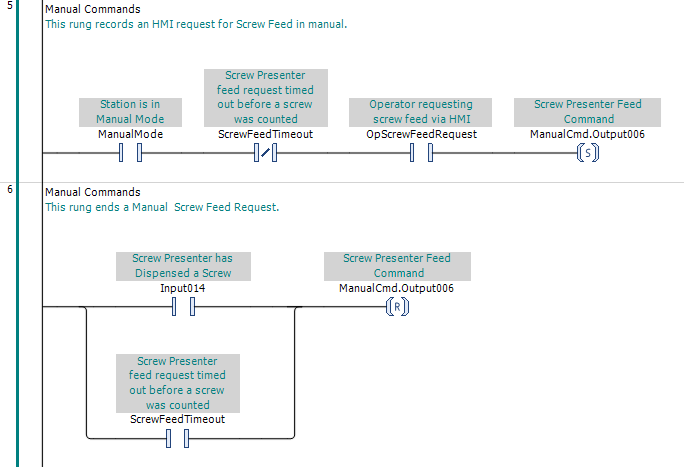
With the HMI screen and shared variables established, we next develop the Screw Feeder logic in ManualOperations. The first rung accepts the operator's request when the workstation is in Manual Mode and no screw feed timeout is active. The second rung resets the manual feed command when a screw is counted or a feed timeout occurs.
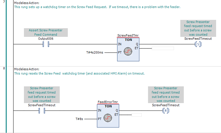
Whenever the Screw Presenter Feed command is asserted, the feeder has a limited time to present a screw. If a screw is not counted before that time expires, the feed request times out and an alarm is generated. We implement this monitoring in ModelessFunctions because it applies to feed requests originating in either Manual Mode or Automatic Mode.
To finish the Screw Feeder programming, we add its output-control rung to OutControl.
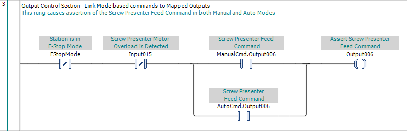
This rung also illustrates why we handle the final output command in OutControl. We place the Screw Presenter overload and E-Stop conditions in series with the parallel Manual and Auto command paths, so either condition can prevent Output006 from being asserted. The Auto command path is already included, although its controlling logic will be developed later. Keeping these common conditions in one rung gives us one place to check when either mode is requesting the output but the command is not being asserted.
We then exercise the Screw Feeder from the HMI and verify its operation. A feed request starts the presenter, the feed command clears when a screw is counted, and the HMI indications follow the observed equipment state. We also verify that a feed request which is not satisfied within 4.2 seconds produces the expected timeout condition and alarm.
During testing, we determine that Screw Presenter has Counted a Screw is not the best description for Input014. What matters to the control program is confirmation that the presenter has dispensed a screw, not the internal counting method used by the presenter. We therefore revise the IO Schedule description to Screw Presenter has Dispensed a Screw and carry that revised description into the HMI and ladder logic. This is a normal part of development: the IO Schedule and program documentation remain working documents and are refined as our understanding of the equipment improves.
The Screw Feeder is now programmed and verified for Manual Mode. The operator can request a screw, monitor the presenter status, and receive an alarm if the presenter overloads or fails to provide a screw within the expected time.
Tightening Tool
The next workstation function we develop in Manual Mode is the Tightening Tool. We begin by reviewing how the tool operates and what information is available to the control program.
From our review of the available I/O, we determine that the Tightening Tool has two output commands and six status inputs available to the control program. Output007 enables the tool, while Output008 enables reverse operation. The Tightening System provides indications that it is ready, that a tightening cycle is in progress, and whether the completed tightening result, torque, and angle are acceptable.
The separate torque and angle results are important because they relate directly to the customer's requirements for the workstation. Every fastening operation must satisfy both the specified torque and angle criteria. A successful tightening result therefore confirms that both requirements were met, while the individual torque and angle indications provide additional information when a tightening result is not acceptable.
Before we decide how to use the tightening-result inputs, we need to understand when the Tightening System turns them on and off. We therefore consult the controller documentation and find that the completed-cycle results remain available until the next tightening cycle produces a new result or until they are reset. More importantly, the controller provides a discrete cycle-reset input that can be operated by the PLC. With two additional wires, we can therefore control when the previous tightening results are cleared rather than simply leaving them in place until the next cycle.
We review the newly identified reset capability with the equipment team, and they agree to add the required wiring using the next available discrete output. Output012, previously identified as a spare at %QX27.3, is reassigned to operate the Tightening System cycle-reset input. We update the IO Schedule accordingly before continuing with the control program.
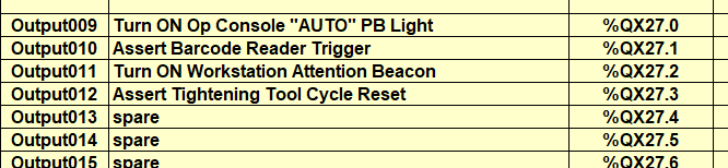
With the available I/O and tightening-result behavior better understood, our next step is to define the alarms associated with the Tightening Tool. The first is straightforward: when Input016 — Tightening System is Ready is FALSE, we generate the "SCREWDRIVER NOT READY" alarm directly from that input.
The torque and angle inputs present another consideration. Both signals indicate a successful result when they are TRUE, while our alarm conditions need to become TRUE when a result fails. We therefore do not use Input020 and Input021 directly as alarm conditions. Instead, when a tightening cycle completes, the control program will need to evaluate the result and, on failure, record separate torque and/or angle error conditions.
Those error bits will then remain active until we reset the completed-cycle results in the Tightening System. When Output012 asserts the cycle reset, we reset the corresponding PLC failure conditions at the same time.
For the torque and angle alarms, we define two new BOOLs in GVL_HMI for the PLC-to-HMI exchange: TighteningTorqueError and TighteningAngleError. These variables will be set by the control program when a completed tightening cycle fails the corresponding criterion, providing positive-TRUE conditions for the HMI alarms.
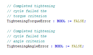
We then add the three Tightening Tool alarms to the Workstation alarm list. The "SCREWDRIVER NOT READY" alarm is activated when PLC01.Input016 is FALSE and GracePeriodOVER is TRUE. This allows the Tightening System time to initialize before reporting that it is not ready. The torque and angle alarms use PLC01.TighteningTorqueError and PLC01.TighteningAngleError, respectively.

With the alarms in place, we next create a new visualization named ScrewDriver for the Tightening Tool Manual Mode controls and indications. We then copy the common header and navigation controls from the existing ScrewFeeder visualization so the new screen uses the same workstation HMI layout and navigation conventions, adding the equipment-screen navigation buttons needed to move between the Screw Feeder and Screwdriver screens.
We then add the controls and indications needed to operate and monitor the Tightening Tool from the ScrewDriver screen. The group shows whether the Tightening System is ready, provides the operator control for reverse operation, and displays whether a tightening cycle is in progress, whether the cycle has completed, and the torque and angle results from the completed cycle.
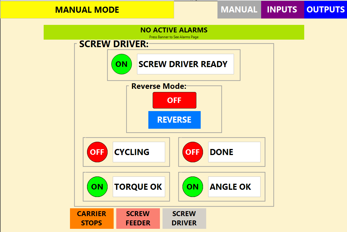
The Tightening Tool must be available for periodic torque verification. In this installation, a maintenance technician brings a torque-test cart to the workstation and uses the screwdriver with the test equipment. The ScrewDriver screen gives the operator and technician the tool status and tightening results needed while performing this work in Manual Mode, without running the workstation's automatic sequence. The torque-test procedure, test interval, and associated record keeping are handled separately from the workstation control program.
We begin the Tightening Tool control logic with its enable command. Because there is no reason to disable the Tightening System during normal workstation operation, we treat this as a modeless action rather than a Manual Mode or Auto Mode command. In OutControl, we assert Output007 — Tightening Tool Enable whenever the workstation is not in E-Stop Mode.
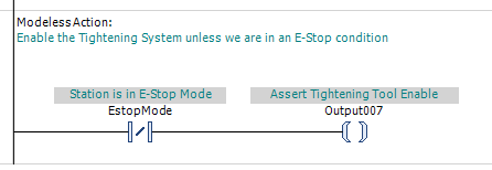
With the Tightening System enabled, we next link the SCREW DRIVER READY indication on the ScrewDriver screen directly to PLC01.Input016 — Tightening System is Ready. When the Tightening System reports that it is ready, the HMI indication turns on and confirms that the screwdriver is available for operation.
The CYCLING indication is also modeless. We link it directly to PLC01.Input019 — Tightening Cycle is in Progress so the HMI shows whenever the Tightening System is actively performing a cycle, regardless of the workstation operating mode.
When the SCREW DRIVER READY indication is on, the operator can start a tightening cycle by pressing the trigger on the screwdriver. We configure the Tightening System to perform the fastening operation using the customer's required torque and angle criteria. Once triggered, the Tightening System controls the cycle and reports its progress and completed results back to the control program.
With the screwdriver enabled, we next develop modeless logic to detect the start and completion of each tightening cycle. Because the Tightening System does not explicitly indicate when the completed results are ready, we allow time for those results to become available before evaluating them.
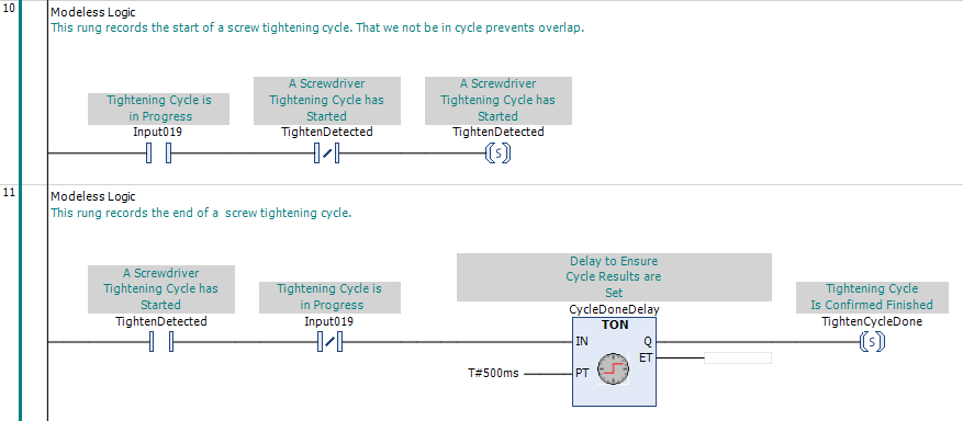
We next establish the torque and angle error indications for a completed screwdriver cycle. This modeless logic also recognizes when the Tightening System has cleared its results, allowing the next cycle to be detected.
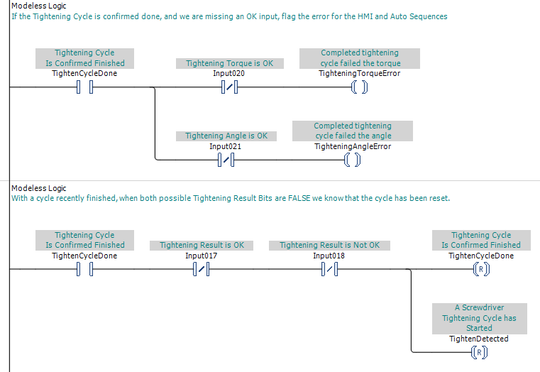
The logic in Figure 51 above recognizes when the Tightening System clears its results. However, it does not command that reset. We next develop the Manual Mode logic that requests the cycle reset.
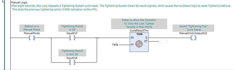
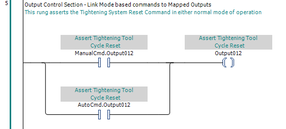
In OutControl, we couple the ManualCmd.Output012 request developed above to the actual mapped Output012 — Tightening Tool Cycle Reset. We also add AutoCmd.Output012 in parallel, knowing that the corresponding Auto Mode logic will be developed later.
Finally, we will need to add the control elements and logic to allow the operator to reverse the action of the screwdriver. Output008 — Tightening Tool Reverse Enable does not cause the screwdriver to run in reverse. It permits reverse operation. The screwdriver itself is equipped with a button to run the tool in reverse.
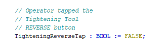
To make the REVERSE control available to the control program, we define TighteningReverseTap in GVL_HMI. The Tap action on the REVERSE button operates this bit, allowing the control program to see when the operator presses the button and respond to that request when appropriate.
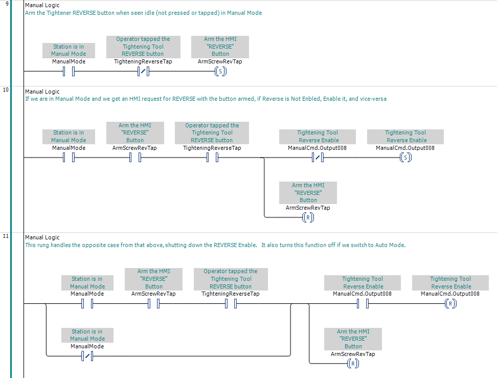
In Manual Mode, we arm the reverse enable/disable requests whenever the REVERSE button is released. The first tap sets ManualCmd.Output008 — Tightening Tool Reverse Enable and disarms the request until the operator releases the button. After the request rearms, a second tap resets the reverse-enable request. We also reset the Manual Mode request whenever the workstation leaves Manual Mode, preventing the reverse-enable command from remaining active after a mode change.
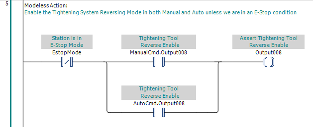
We complete the screwdriver reverse-enable function in OutControl, where ManualCmd.Output008 and AutoCmd.Output008 provide parallel requests to assert Output008 — Tightening Tool Reverse Enable. Either request enables reverse operation, provided the workstation is not in E-Stop Mode.
With the Tightening Tool logic complete, we ask the maintenance technician to bring the torque-test cart to the workstation and verify the screwdriver with us. Operating in Manual Mode, we confirm the SCREW DRIVER READY and CYCLING indications, observe the completed torque and angle results, verify that the results clear as intended, and confirm that the REVERSE control properly enables and disables reverse operation.
With the Tightening Tool enabled, monitored, reset, and reversible from Manual Mode, we now have a screwdriver that can be operated, tested, and recovered independently of the workstation's automatic sequence.
Carrier Lift
The next workstation function we develop in Manual Mode is the lift function of the Carrier Lift and Spin. We begin by reviewing how the lift operates and what commands and feedback are available to the control program.
From our review of the available I/O, we determine that the lift function of the Carrier Lift and Spin has two discrete output commands: Raise and Lower. The lift also provides discrete indications that it is fully raised and fully lowered.
The light curtain separately affects the safe operation of the lift. If the light curtain is BREACHED, the safety system removes power from the lift solenoids. If the light curtain is MUTED, the control program inhibits the Raise and Lower commands. Normal lift operation therefore requires the light curtain to be INTACT.
Unlike the carrier stops, the lift uses separate detented solenoid valves for the raise and lower commands. Each movement therefore requires a specific command from the control program; removing a command does not cause the lift to return automatically in the opposite direction.
The fully raised and fully lowered inputs are important to the completed workstation, particularly for later automatic sequencing, but they do not need to prevent normal Manual Mode operation. One purpose of Manual Mode is to allow the PLC Pro to raise and lower the lift deliberately while verifying that these feedback devices operate and report correctly.
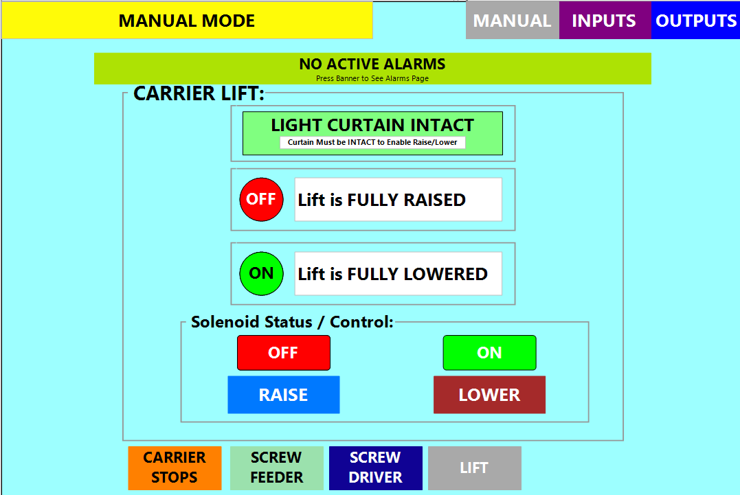
We will also include the light-curtain status on the Carrier Lift Manual Mode screen. A RAISE or LOWER command will only be permitted when the light curtain is clear and not muted, so the operator needs to be able to see that condition while testing the lift. The lift controls therefore require two command buttons and five status indications: raise command, lower command, fully raised, fully lowered, and light-curtain status.
We begin the HMI work by creating a new visualization named CarrierLift. As with the other equipment screens, we copy the common workstation header and navigation controls from an existing visualization before adding the controls and indications needed to develop and verify the Lift Raise/Lower function in Manual Mode.
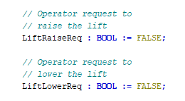
To connect the lift controls to the control program, we define two BOOLs in GVL_HMI for the RAISE and LOWER buttons. As with the other Manual Mode controls, the Tap action on each button makes its request TRUE while the operator is pressing it and FALSE when the button is released.
For the light curtain, we use a single status indication that displays INTACT, BREACHED, or MUTED, with a distinct color for each condition. We also identify INTACT as the condition required for lift operation so an operator does not have to infer that requirement from the display color alone.
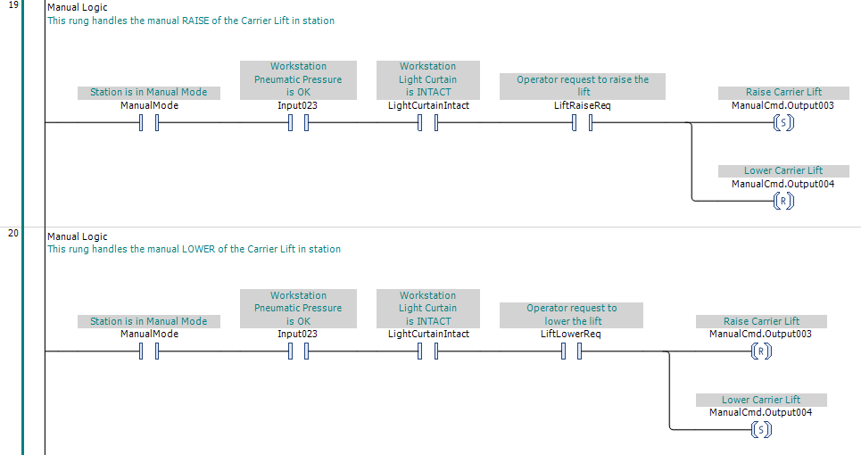
Earlier in the tutorial, we established LightCurtainIntact in ModelessFunctions to identify when the light curtain is clear and not muted. We now use this condition to permit the Carrier Lift's RAISE and LOWER commands only when the light curtain is INTACT.
We next develop the Manual Mode Raise and Lower logic for the Carrier Lift. Each operator request is accepted only when workstation pneumatic pressure is available and the light curtain is INTACT. Because the lift uses separate detented Raise and Lower valves, the logic also makes sure that commanding one direction removes the command for the other.
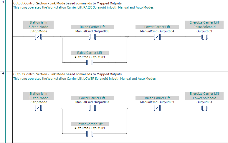
With the Carrier Lift Raise and Lower commands established in ManualOperations, we next add the corresponding rungs in OutControl. These rungs combine the Manual and Auto requests to operate the lift solenoids, while providing E-Stop inhibition and opposing-command interlocks. As with our other mapped outputs, we use ordinary, nonlatched coils.
With the Carrier Lift controls and indications in place, we test the function in Manual Mode. We verify that the RAISE and LOWER controls operate the expected outputs, confirm the fully raised and fully lowered feedback as the lift moves, and verify that lift commands are inhibited unless the light curtain is INTACT. We also confirm that the light-curtain status correctly displays INTACT, BREACHED, and MUTED.
With the Carrier Lift operating correctly in Manual Mode, the PLC Pro can now raise and lower the lift deliberately, observe the command and position feedback, and verify the light-curtain conditions that govern lift operation. These proven lift functions and indications will later be used by the workstation's automatic sequences.
Carrier Rotate Preparation
The final workstation function we develop in Manual Mode is the rotate function of the Carrier Lift and Spin. We begin by reviewing how the carrier is rotated and registered, and what conditions, commands, and feedback are needed to operate and verify the function.
The carrier rotate function is provided by a servo motor and drive. We will use the servo's positioning capability, configured to operate in degrees, to command each 180-degree rotation of the carrier. This allows the drive to control acceleration, deceleration, and final position rather than relying on a sensor to initiate the normal stopping operation.
We begin by identifying the physical IO used during the Carrier Rotate cycle. Output005 energizes the spring-return solenoid valve to retract the Carrier Lock Pin, allowing the carrier to rotate freely. Two discrete inputs confirm the fully extended and fully retracted pin positions, while the registration photoeye detects either of the two reflective targets on the carrier.
The Carrier Rotate function also depends on the existing Light Curtain. A BREACHED light curtain initiates a stop through the safety system, independently of the control program. Inasmuch as an operator may be inside the curtain when it is either BREACHED or MUTED, the control program must confirm that the light curtain is INTACT before permitting, commanding, or continuing rotation.
The PLC Pro is expected to understand and configure intelligent devices such as our servo drive, not simply exchange commands and feedback with them. The equipment team depends on us to study the manufacturer's documentation, understand the available capabilities, and establish the configuration needed for the intended operation. We must determine how the drive will perform its required functions and interact with the rest of the equipment before committing those decisions to control logic.
Most of the commands and feedback required for Carrier Rotate are exchanged with the servo drive through EtherCAT communications rather than physical IO points. The control program uses this interface to command and monitor the servo's operation, including positioning, speed, torque, and drive status. We need to identify the available communications data and determine which signals are required to support homing, normal rotation, interruption recovery, and the mechanical handoff to the Carrier Lock Pin.
Reviewing the Carrier Rotate communications requirements reveals a problem we did not address when developing the IO Schedule. The control program can recognize a loss of EtherCAT communications with the servo drive, but cannot command the drive to stop through a failed communications link. We therefore need a hardwired means of initiating a stop, independent of EtherCAT communications. We initially consider using the existing E-Stop system to provide that stopping response.
When we review this proposal with the equipment and electrical teams, they point out that the E-Stop system applies to the entire assembly line, not just our workstation. Initiating an assembly-line E-Stop because of a local drive communications failure would unnecessarily interrupt the entire installation. Instead, we agree to provide a separate hardwired permissive for the Carrier Rotate drive, allowing us to stop the servo independently of EtherCAT communications without affecting the rest of the assembly line.
We therefore add Output013 — Carrier Rotate Drive Comm OK to the IO Schedule. This output energizes a relay in the servo drive's hardwired rotation permissive circuit whenever EtherCAT communications with the drive are healthy. When the control program detects a communications failure, it turns Output013 OFF, dropping the relay and initiating the drive's configured stopping response. This allows us to stop the Carrier Rotate drive without placing the entire assembly line into E-Stop Mode.
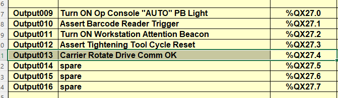
With the physical IO established, we can begin developing the Carrier Rotate operation. Our first consideration is determining the carrier's position. We cannot assume that the servo drive knows where the carrier is when the workstation is placed into service, so we must establish a known starting position (HOME). We will accomplish this by developing a Homing Sequence, using the registration photoeye and Carrier Lock Pin to provide the servo with a valid position reference.
To establish the carrier's HOME position, we will use the servo drive's Profile Velocity mode to rotate the turntable at a slow, controlled speed. The carrier always rotates in the same direction, whether performing a Homing Sequence or a normal 180-degree rotation. As the carrier rotates, the control program monitors the registration photoeye to detect the approaching mechanical registration position.
When a reflector is detected, the control program will command the Carrier Lock Pin to extend. This event will also be used to set the RotateTargetSpeed to zero, initiating servo deceleration. We will need the pin to ride against the underside of the turntable until its locating cavity arrives. The rounded, tapered end of the pin will then guide it into the cavity, stopping any remaining rotation. A configured drive torque limit will serve to protect the servo and Lock Pin during engagement and final stopping.
Once the Carrier Lock Pin is confirmed fully extended and rotation has stopped, we will use the servo drive's Homing function to establish the current position as zero degrees. This establishes the carrier's HOME position, providing a known reference for subsequent rotations.
Once HOME has been established, we decide that we will switch the servo drive to Profile Position mode. This will allow us to command a simple 180-degree rotation in the established direction. In this mode, the drive controls acceleration, deceleration, and positioning, bringing the carrier very close to its intended final position.
On completion of the commanded rotation, we will use the registration photoeye to confirm that the carrier is within the registration range. If a target is detected, we will disable servo operation and command the Carrier Lock Pin to extend. This allows the tapered pin to establish the final mechanical position without resistance from the servo's position control.
With the Carrier Lock Pin confirmed fully extended, we will again use the servo drive's Homing function to establish the current position as zero degrees. By re-establishing HOME after each rotation, we can prevent small positioning errors from accumulating over successive cycles.
For interruption recovery, once the conditions responsible for the interruption have been cleared and any required reset completed, we decide the best approach will be to initiate the Homing Sequence rather than attempting to complete the interrupted rotation. This allows us to ensure that we return to a registered position and establish a new HOME.
With our operating strategies for the Homing Sequence, normal rotation, and interruption recovery defined, we next examine the servo drive's capabilities and EtherCAT interface to determine what is needed to implement them. We need to select operating modes, establish rotation speeds, acceleration and deceleration, configure torque limits, control servo enable and shutdown, command positioning, and establish HOME. We must also identify the drive status and position information needed to verify these operations and support recovery.
Not everything required for these operations needs to be exchanged with the PLC. Some information must be commanded or monitored by the control program through EtherCAT, while other operating parameters can be established directly in the drive's configuration. The PLC Pro is responsible for studying the drive documentation, determining which approach is appropriate for each requirement, and establishing the necessary drive configuration before developing the corresponding control logic.
We begin with the drive status inputs that apply regardless of the selected operating mode. The drive provides Fault and Warning indications to identify abnormal conditions during the Homing Sequence, normal rotation, and interruption recovery. These signals will support our drive diagnostics and HMI alarms.
We also need to establish an operable state for the servo drive. The servo drive uses the Switch On, Enable Voltage, Quick Stop, and Enable Operation bits in its Controlword. When the drive has accepted these conditions, it returns Operation Enabled. We also establish a HOMED status in the control program following successful completion of the Homing Sequence. Both conditions are required before permitting normal rotation.
The drive provides Position Actual Value through EtherCAT object 6064h. This allows the control program to monitor the servo's actual position and compare it with the expected position to help identify positioning problems. We will address the associated fault conditions when developing the Carrier Rotate alarms.
The drive also provides Torque Actual Value through EtherCAT object 6077h. We will use this feedback to monitor motor torque during commissioning, allowing us to establish appropriate torque limits for the Homing Sequence and normal rotation.
We also need information about the drive's operating mode and stopped condition. The drive returns its current operating mode through EtherCAT object 6061h — Modes of Operation Display, allowing the control program to verify that the requested mode has been accepted. Zero Speed Detection indicates when motor speed has fallen below the drive's configured zero-speed threshold. These signals help us coordinate mode changes, stopping operations, and recovery.
For the Homing Sequence, we first use Modes of Operation Display to confirm that the drive has entered Profile Velocity mode. Velocity Actual Value allows us to monitor the servo's actual speed as we locate the registration reflector and decelerate toward the mechanical HOME position.
Once mechanical registration is complete, we select Homing mode and confirm that the drive has accepted it. In this mode, the drive provides Homing Attained, Homing Error, and Target Reached indications through its Statusword (6041h), allowing us to verify that the HOME position has been successfully established.
For normal rotation, we first use Modes of Operation Display to confirm that the drive has entered Profile Position mode. In this mode, the drive provides Set-point Acknowledge and Target Reached indications through its Statusword (6041h), allowing the control program to confirm acceptance and completion of the commanded 180-degree rotation. We also use Position Actual Value to monitor the positioning operation.
For interruption recovery, we do not require a separate drive operating mode. We execute the same Homing Sequence used to establish HOME. Because we use the same sequence and drive feedback, no additional drive inputs are required.
We next identify the commands the control program must send to the servo drive through EtherCAT. We begin with Modes of Operation, EtherCAT object 6060h. The control program will set this value when selecting among Profile Velocity mode (3), Homing mode (6), and Profile Position mode (1), based on our current operation.
We also use the drive's Controlword, EtherCAT object 6040h, to manage servo operation. The Switch On, Enable Voltage, Quick Stop, and Enable Operation bits establish the conditions required to operate the servo.
In addition to the drive-enable commands, the Controlword provides Fault Reset and HALT. For Homing mode, we will use Homing Operation Start. For Profile Position mode, we will use New Set-point, Change Set Immediately, and Absolute/Relative. These functions will be included in our drive output mapping.
We will also use the Controlword's torque-limit selection bits to select the configured torque limit appropriate to the current operation.
In Profile Velocity mode, the control program provides Target Velocity through EtherCAT object 60FFh. In Profile Position mode, the control program provides Target Position through EtherCAT object 607Ah.
We will establish the drive's Profile Velocity, Profile Acceleration, and Profile Deceleration settings during commissioning and retain them in the drive configuration. These parameters determine the motion characteristics of the servo and do not require adjustment by the control program during normal operation.
We also need to establish the drive's Homing Method. We select Method 37, which establishes the current position as HOME. Since this selection will not change during operation, we can establish it in the drive configuration rather than sending it as a PLC output.
We also need to establish motor torque limits to protect the Carrier Rotate mechanism during the Homing Sequence and normal rotation. The drive allows us to configure two torque limits and select between them through the Controlword. We will establish the appropriate limits during commissioning and have the control program select the limit appropriate to the current operation.
Our IO mapping is incomplete until we include the input and output bits exchanged with the servo drive through EtherCAT. Although these are not physical IO points, they still require mapping for use by the PLC Pro in developing and maintaining the control program.
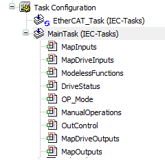
In order to map the servo-drive communication bits, we add two new Ladder program POUs beneath the Application. We name the programs MapDriveInputs and MapDriveOutputs. These programs will handle the status and command bits exchanged with the drive.
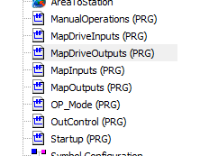
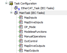
We then add both programs to MainTask and place MapDriveInputs immediately after MapInputs, with MapDriveOutputs immediately before MapOutputs. This keeps all input mapping ahead of the workstation control logic and all output mapping after it.
Before developing the drive input-mapping Ladder, we review the required status bits in the Servo Drive portion of our IO Schedule. Some bits have different meanings depending on the drive's operating mode, so we need to understand their functions before assigning meaningful global BOOL names. We distinguish between the operating status of the drive and the motion of the servo motor, assigning variable names accordingly. We record the assigned variable names in the IO Schedule.
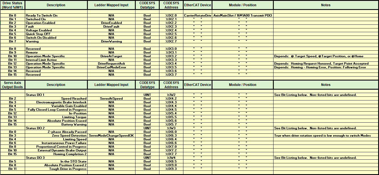
We next review the command bits sent from the control program to the servo drive. Using the Controlword functions identified earlier, we assign meaningful global BOOL names to the required commands and record them in the IO Schedule. These variables will be mapped to their corresponding EtherCAT output bits in MapDriveOutputs.
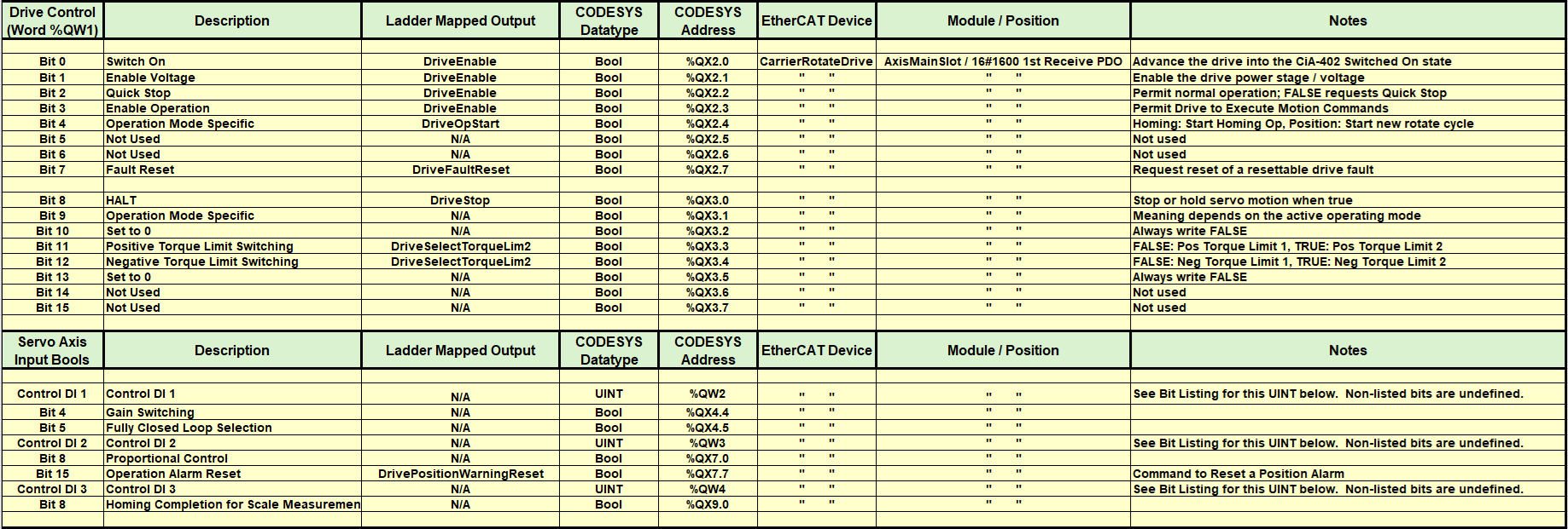
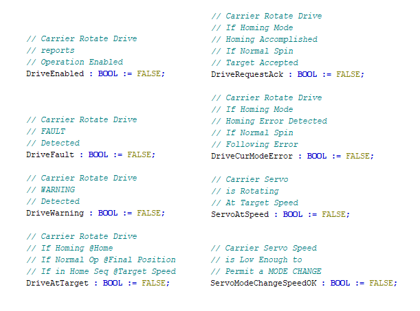
Before developing the input-mapping Ladder, we add the eight BOOL inputs identified in our IO Schedule to GVL_IO. Each variable is initialized to FALSE and given a description of the drive or servo condition it represents. These global variables will receive the mapped EtherCAT input states, making them available to the control program and HMI.
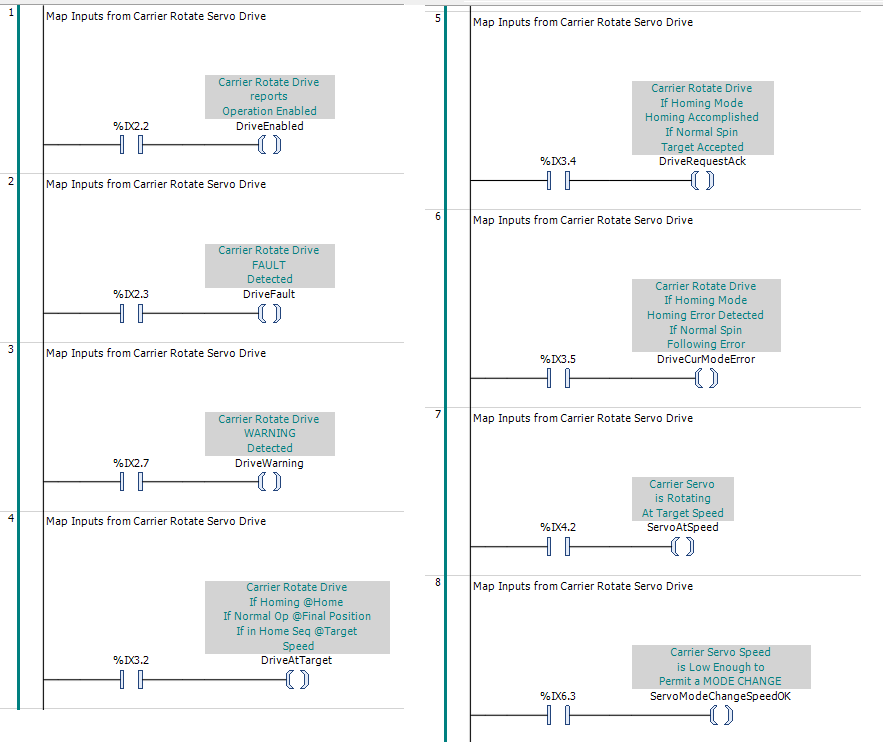
With the global BOOLs declared, we develop the Ladder in MapDriveInputs. Each rung reads a drive input bit from its EtherCAT address and assigns its state to the corresponding global BOOL. For the mode-specific indications, we include comments explaining what each bit represents in the applicable operating modes. This completes our discrete drive-input mapping, allowing the control program to use meaningful variable names rather than EtherCAT addresses.
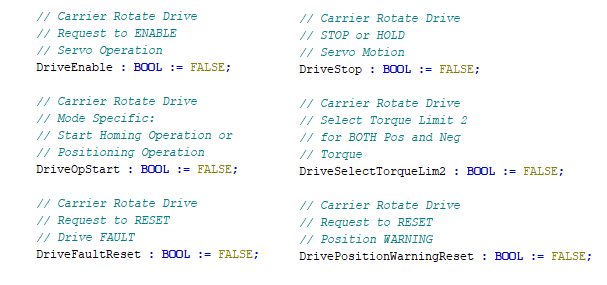
Before developing the output-mapping Ladder, we add the six drive command BOOLs identified in our IO Schedule to GVL_IO. Each variable is initialized to FALSE and given a description of the command it represents. These global variables will be controlled by the operating logic and mapped to their corresponding EtherCAT output bits in MapDriveOutputs. Some commands control multiple EtherCAT bits, but require only one global BOOL.
With the six global BOOLs declared, we develop the Ladder in MapDriveOutputs. Each rung uses a global command BOOL to control the corresponding EtherCAT output bit or bits identified in our IO Schedule. The DriveEnable command controls four Controlword bits, while DriveSelectTorqueLim2 controls both torque-limit selection bits. We include comments describing each command so its purpose remains clear when examining or troubleshooting the Ladder.
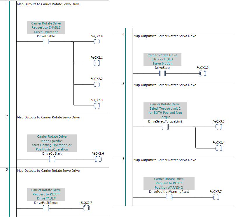
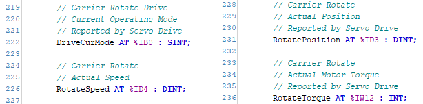
We next address the servo-drive inputs that provide numeric values rather than individual BOOL states. When an address such as %ID4 is entered directly in Ladder, CODESYS interprets it as a DWORD, producing a datatype warning when the value is transferred to a DINT variable. We avoid this problem by using typed AT declarations, which associate each variable directly with its EtherCAT address and specify the correct datatype. This also eliminates the need for additional Ladder mapping instructions.
In GVL_IO, we declare four numeric drive inputs using the addresses and datatypes identified in the EtherCAT IO Mapping. DriveCurMode is declared as a SINT, RotateSpeed and RotatePosition as DINTs, and RotateTorque as an INT. These variables provide the control program and HMI with direct access to the drive's current operating mode, actual speed, actual position, and actual torque.
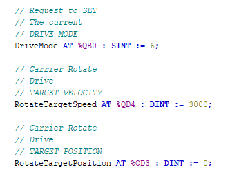
We next declare the three numeric values sent to the servo drive through EtherCAT. In GVL_IO, we declare DriveMode as a SINT, and RotateTargetSpeed and RotateTargetPosition as DINTs. As with the numeric inputs, we use typed AT declarations to associate each variable directly with its EtherCAT address. We initialize DriveMode to 6, requesting Homing Mode. We initialize the target speed to 3000 and the target position to zero. The control program will update these commands as required by the operating sequences.
With the IO now defined and mapped, we begin developing the Carrier Rotate alarms. Two alarm conditions are reported directly by the servo drive. The mapped DriveFault input provides an alarm in the Error class, while DriveWarning provides an alarm in the Warning class. Since the drive may report temporary fault or warning conditions during startup, we qualify both alarm activation conditions with GracePeriodOVER. Each alarm clears when its corresponding status bit returns to FALSE.

We now add the drive communications alarm identified earlier during development of ModelessFunctions. We configure an Error class alarm in the HMI with the message "CARRIER DRIVE COMM INTERFACE NOT OPERATIONAL". The alarm activates when CarrierDriveCommOK is FALSE and clears when it returns to TRUE. This alerts the operator whenever the drive's EtherCAT interface is unavailable.
Reviewing the existing CarrierDriveCommOK logic draws our attention to an oversight in the MainTask execution order. We currently execute ModelessFunctions after OP_Mode, even though diagnostic conditions established in ModelessFunctions can directly affect operating-mode decisions.
We therefore move ModelessFunctions immediately after MapDriveInputs in the MainTask execution order. This ensures that the diagnostic conditions established in ModelessFunctions are available to OP_Mode and all subsequent control logic during the same scan.
We next consider the servo drive's status indications or alarms that depend on its operating mode. Because certain status bits have different meanings in different operating modes, we must establish the drive's current operating mode before interpreting these indications. We will develop this logic separately from the general diagnostics already handled in ModelessFunctions by creating a new DriveStatus POU, and placing it directly below.
We begin by declaring four BOOL variables in GVL_General to identify the servo drive's three operating modes and recognize when none of these modes is active. Each variable is initialized to FALSE and includes a description of the operating condition it represents.
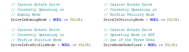
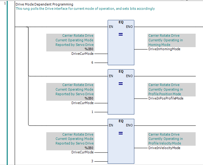
We begin the DriveStatus Ladder with three EQ comparisons that examine DriveCurMode to determine which of our three operating modes is active. The results establish DriveInHomingMode, DriveInPosProfileMode, and DriveInVelocityMode, making the current operating mode available to the control program.
We also need to recognize when the servo drive is operating in a mode not defined for our application, but only after the startup grace period has expired. In DriveStatus, we use GracePeriodOVER to qualify the logic that establishes DriveModeUndefined.

We also configure an Error class alarm in the HMI with the message "CARRIER ROTATE DRIVE OPERATING MODE UNDEFINED". The alarm activates when DriveModeUndefined is TRUE and clears when the variable returns to FALSE. This alerts the operator when the servo drive is not operating in one of our three defined modes.
The servo drive's DriveCurModeError input reports different error conditions depending on its operating mode. In Homing mode, it indicates a Homing Error, while in Profile Position mode, it indicates a Following Error. We declare separate global BOOLs in GVL_HMI, develop the Ladder in DriveStatus to identify each condition, and configure separate Error class alarms in the HMI.
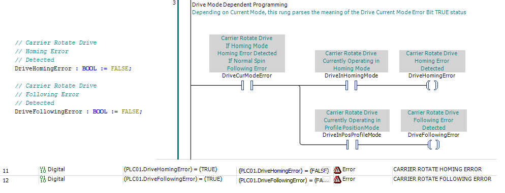
As we continue developing the control program, we expect to identify additional conditions that warrant alarms. Our HMI alarm list is therefore a work in progress. We will define each new alarm and develop the necessary detection logic as we encounter the conditions that require it.
We next create a new CODESYS HMI visualization named Rotation to provide the controls and indications needed for manual operation of the Carrier Rotate function. We arrange these elements as shown below.
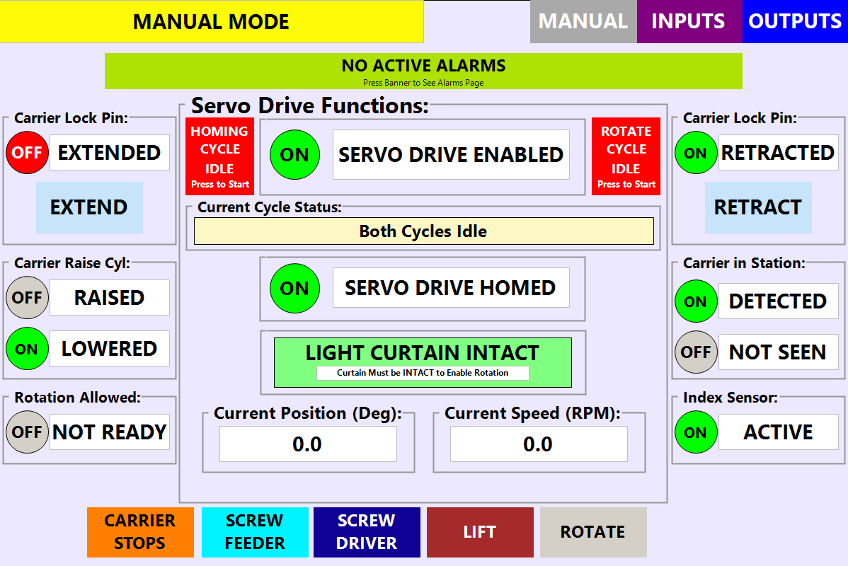
The Rotation screen is organized around the servo drive and the equipment conditions that support carrier rotation. The central area displays the servo's operating status, position, speed, and current cycle status, together with the light-curtain condition. Along the sides, we provide controls and position indications for the Carrier Lock Pin, position feedback from the Carrier Lift, carrier-presence and registration indications, and the status of the conditions permitting rotation. This arrangement gives the operator a comprehensive view of the Carrier Rotate function during manual operation and troubleshooting.
The Rotation screen provides four operator controls. The EXTEND and RETRACT buttons operate the Carrier Lock Pin, with separate indications confirming its position. The HOMING CYCLE and ROTATE CYCLE buttons initiate their respective sequences and also serve as cycle-status indicators.
Our next step will be to develop the Manual Mode controls for the Carrier Lock Pin. We begin by adding two BOOL variables to GVL_HMI: CarrierLockPinExtendReq and CarrierLockPinRetractReq. These variables carry the operator's EXTEND and RETRACT requests from the HMI to the control program.
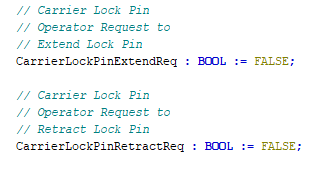
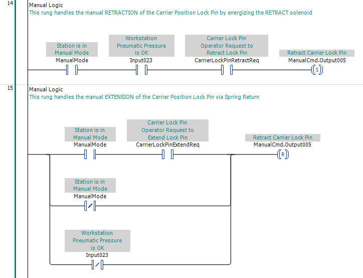
We next develop the Carrier Lock Pin logic in ManualOperations, providing the operator with independent control of the pin without running a carrier-rotation sequence. This allows us to exercise the mechanism and verify its position feedback before developing the Homing and Normal Rotation Sequences.
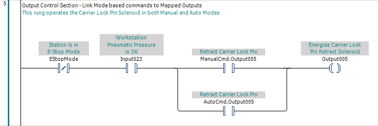
With the Carrier Lock Pin Manual commands established, we need to connect them to the mapped output. We add a rung in OutControl that energizes Output005 when either ManualCmd.Output005 or AutoCmd.Output005 requests retraction, provided the workstation is not in E-Stop Mode and pneumatic pressure is available. When neither command is present, the solenoid deenergizes, allowing the spring-return valve to extend the Carrier Lock Pin.
We then exercise the Carrier Lock Pin using the EXTEND and RETRACT controls on the Rotation screen. The pin retracts when commanded and returns to its extended position when the retract command is removed. The HMI position indications correctly reflect the fully extended and fully retracted conditions. We observe no unexpected behavior during testing.
We now have the Manual Mode controls and indications needed to operate the individual workstation equipment functions. We have also established the supporting modeless functions, drive status monitoring, alarm handling, and output control needed to develop and verify these operations. Together, these provide a foundation for commissioning the workstation and developing its automatic operations.
We next develop two modeless sequences that coordinate multiple equipment actions: the Carrier Homing Sequence and the Carrier Normal Rotation Sequence. Each sequence is developed in a separate tutorial, allowing us to address its operating requirements, control logic, and recovery behavior in detail. Both sequences are available for Manual Mode testing and subsequent use during automatic operation.