Purpose
In this tutorial, we develop the Carrier Homing sequence for our example workstation, applying established PLC Pro Sequencing methods to a sequence that operates independently of the workstation's automatic cycle. We develop the logic needed to prepare the equipment, control carrier rotation, and establish the carrier's mechanical HOME position. This modeless sequence operates in Manual Mode and will also be called by the Automatic Build Sequence whenever carrier rotation is interrupted.
In Sequence Preparation, we establish the programming foundation for the Carrier Homing sequence. We create the CarrierHomeSeq program, develop the reusable AutoSequence structure, and establish a method for organizing and documenting individual sequence steps. We also develop supporting servo-drive control logic, including drive-enable management and automatic fault-reset handling, before beginning the actual sequence programming.
In Permissives and Sequence Start, we apply four fundamental elements of PLC Pro Sequencing:
- OkToContinue: Confirms that the resources and conditions required for continued sequence operation are available.
- OkToStart: Confirms that conditions permit a new sequence cycle to begin.
- NoConflict: Confirms that no conflicting operations prevent sequence activation.
- Trigger: Establishes that a request to initiate the sequence has been received.
We develop the Ladder logic for these four elements and use them to establish sequence activation.
In Sequence Steps, we develop seven steps that prepare the workstation, establish the servo drive's operating mode, control carrier rotation, and establish mechanical HOME. Along the way, we discover and correct missing operations, demonstrating how sequence development evolves as we examine the equipment requirements. We also establish how the sequence ends normally and identify other conditions that trigger a sequence RESET. Finally, we set up the TooLong timer to detect problems with the overall sequence execution.
In Link Sequence Steps to Outputs, we develop the equipment commands required by the homing sequence. Because this sequence operates in Manual Mode, we must prevent conflicting operator commands while allowing the sequence to control the Carrier Feed Stop, Carrier Lift, and Carrier Lock Pin. We also establish the servo drive's operating mode and develop the commands that initiate and stop carrier rotation, including the HALT response required when the sequence is interrupted.
In Sequence RESET, we develop the actions performed when the homing sequence receives its RESET command. We clear the sequence status and step memory, ensure the servo drive is commanded to HALT, and restore the HMI status message to IDLE. We also initialize that same message during the first PLC scan. Finally, we test the completed sequence and adjust the servo drive parameters to achieve smooth, predictable operation.
Sequence Preparation
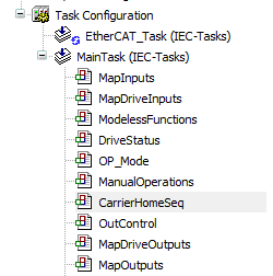
We begin development of the Carrier Homing sequence by creating a new Ladder Program POU named CarrierHomeSeq. We add this program to MainTask, immediately after ManualOperations and before OutControl. This placement allows the homing logic to evaluate operator requests and the current workstation conditions before the output-control logic executes.
This workstation will use several automatic sequences to coordinate equipment operations. Some sequences will be available in both Manual Mode and Auto Mode, while others will operate only during the automatic cycle. Regardless of how they are initiated, all will use the same PLC Pro Sequencing structure. This will provide a consistent organization for the control, status, and timing variables associated with each sequence.
One of the tools we use to organize and implement PLC Pro Sequencing is a common memory structure, or user-defined data type, that can be applied to any sequence. This structure groups the variables needed to control, monitor, and document a sequence into a consistent arrangement. By using the same structure for every sequence, we establish a common programming framework while allowing each sequence to operate independently.
This consistency extends beyond programming. It provides operators and maintenance personnel with a common framework for understanding sequence operation, recognizing operating conditions, and troubleshooting problems after commissioning. Familiarity with the standard sequencing elements allows maintenance personnel to identify and communicate specific problems, such as a missing starting permissive, rather than reporting only that the equipment will not run.
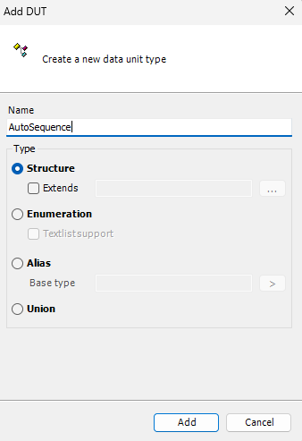
We begin by creating a new memory structure, commonly called a user-defined data type (UDT) on other PLC platforms. In CODESYS, we create a Data Unit Type (DUT) object, select Structure (STRUCT) as its type, and name it AutoSequence.
As we develop this structure, we will add the individual variables needed to implement the established PLC Pro Sequencing method, examining the purpose of each member and selecting an appropriate data type. The completed structure will provide a consistent set of sequencing variables that we can use for every automatic sequence developed in the workstation control program. The linked Methods section provides detailed explanations of the individual sequencing elements and their operation.
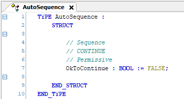
The first member we add to AutoSequence is OkToContinue, declared as a BOOL. This permissive is used to define the conditions required for each sequence's continued operation. While this permissive is FALSE, a sequence remains frozen in its current state.
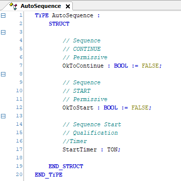
We next add OkToStart, a BOOL that indicates whether the sequence is permitted to start. We also add StartTimer, a TON (On-Delay Timer) used to qualify the starting conditions before OkToStart becomes TRUE. Both members are part of the standard AutoSequence structure.
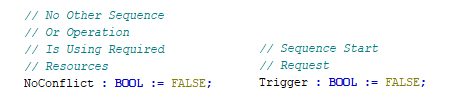
We next add two BOOL members: NoConflict and Trigger. NoConflict indicates that no other sequence or equipment operation is using a resource required by this sequence. Trigger provides the request to initiate the sequence.
We next add two BOOL members associated with sequence execution. Active indicates that the sequence is running, while OkToAdvance authorizes the sequence to advance from its current step to the next. Both are initialized to FALSE.

We would like to declare a DWORD named Step within our AutoSequence structure. This would allow us to address individual sequence steps as bits within the DWORD and reset all steps unambiguously with a single instruction.
In most PLC programming environments, we could also provide a descriptive comment for each individual bit within the proposed DWORD. Unfortunately, CODESYS does not provide a convenient way to associate comments with individual DWORD bits. This presents a problem because PLC Pro Methods require that each sequence step's purpose be documented directly in the ladder program. This requirement is non-negotiable when developing control programs that can be readily understood and maintained by maintenance personnel.
To accommodate this requirement in CODESYS, we create a new global variable list named GVL_SequenceSteps. This list will contain the memory declarations for the individual steps of each sequence, keeping them separate from the common AutoSequence structure.
We begin by declaring a DWORD named HomeSeqSteps to contain the steps of our Carrier Homing sequence. We assign it an unused absolute memory address. This gives the sequence a clearly identified block of memory that we can reset with a single instruction.
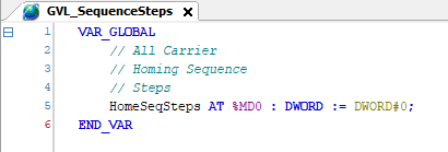
As we develop the Carrier Homing sequence, we will add individual HomeStep_nn BOOL declarations to GVL_SequenceSteps as each step is established. Each declaration will use an absolute address corresponding to a bit in HomeSeqSteps and include a comment describing that step's specific function. This will allow us to develop and document the sequence one step at a time.
We next add NormalDone, a BOOL indicating that the sequence has completed normally and any required completion handshakes can be established. We also add Reset, a BOOL used to command the sequence to reset.

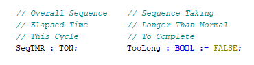
We next add SeqTMR, a TON that measures the elapsed time of the current sequence cycle. We also add TooLong, a BOOL indicating that the sequence is taking longer than normal to complete.
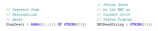
To provide information about sequence progress on the HMI, we define StepDescr, an array of 32 strings containing the descriptions associated with individual sequence steps. HMIReadString holds the description of the current cycle status for display on the HMI.
Having verified that our AutoSequence structure provides the common variables required by the PLC Pro Sequencing method, we consider its development complete. The individual sequence steps are maintained separately, as described above. We can now reuse this structure for the Carrier Homing sequence, Normal Rotation Sequence, and every subsequent automatic sequence we develop.
With the AutoSequence structure complete and our approach to documenting individual sequence steps established, we have the tools needed to apply the PLC Pro Sequencing method throughout the workstation.
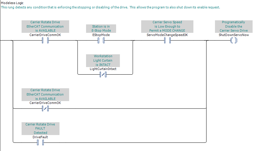
The next preparation step is to establish how we handle the Carrier Rotate servo drive DriveEnable output. Just as we locate the brakes before operating an unfamiliar vehicle, we need to understand how the drive responds to stopping conditions. The workstation safety system handles the actual stopping; our control program must determine when to withdraw the drive-enable request.
We identify three conditions that affect when the control program should withdraw the DriveEnable request. When a safety stop occurs and communications with the servo drive remain operational, we monitor its Zero Speed Detection feedback and withdraw the request once the drive reports zero speed. When communications are lost, we cannot rely on that feedback, so we withdraw the request immediately. A reported servo-drive fault also causes us to withdraw the request immediately. The workstation safety system independently handles safety-related stopping, while the servo drive manages its own fault response.
We next address recovery from Carrier Rotate servo-drive faults. When the drive reports a fault, our control program attempts to reset it automatically. If the fault persists, we repeat the reset request at six-second intervals, allowing a maximum of three attempts. If the drive remains faulted after those attempts, we stop requesting resets and generate an alarm indicating that maintenance intervention is required.
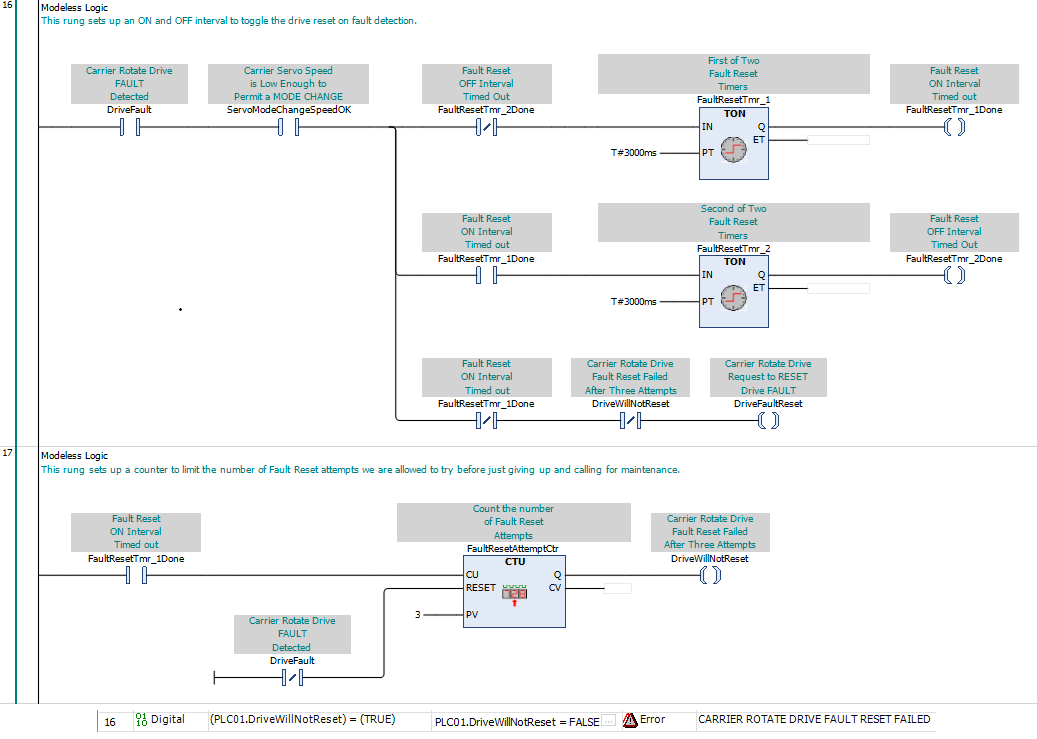
At this point we have addressed the preparation requirements identified so far, including the common sequencing structure and the control functions needed to support sequence development. Additional requirements may become apparent as we proceed, but we have established enough of the foundation to begin developing the Carrier Homing sequence.
Permissives and Sequence Start
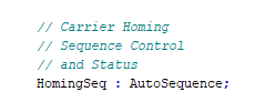
We begin developing the Carrier Homing sequence by declaring HomingSeq in GVL_General as an instance of our AutoSequence structure. This provides the sequence with its own set of control, status, and timing variables while retaining the common organization established by PLC Pro Sequencing.
Following the PLC Pro Sequencing method, we begin with HomingSeq.OkToContinue. This permissive establishes whether conditions allow the homing sequence to continue operating.
In evaluating the requirements for HomingSeq.OkToContinue, we identify six resources that must remain available: workstation output power, servo-drive communications, an intact light curtain, pneumatic pressure, a fault-free servo drive, and confirmation that the drive is enabled. We also require that the workstation is not in E-Stop Mode.
With six resource conditions and the E-Stop operating state to evaluate, our HomingSeq.OkToContinue rung becomes too wide to display on a single screen at normal magnification. We need a way to organize these checks into smaller, more manageable Ladder rungs.
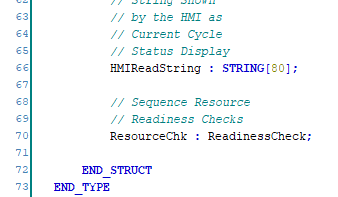
To organize these checks, we create a new STRUCT named ReadinessCheck. This structure provides a common way to evaluate resource availability without requiring every condition to appear in the sequence's OkToContinue rung.
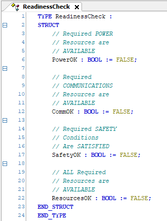
Since each sequence must evaluate its own resource availability, we add a member named ResourceChk to our AutoSequence structure, declaring it as an instance of the ReadinessCheck structure we just created. This gives every sequence its own set of readiness variables while maintaining the common organization of PLC Pro Sequencing.
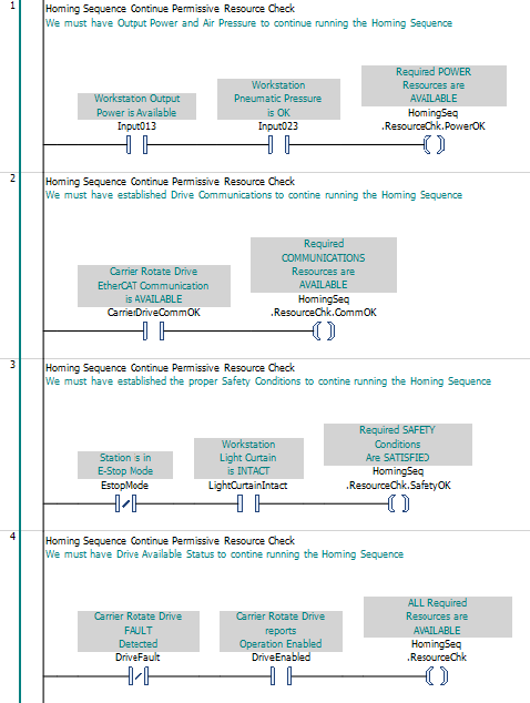
With ResourceChk available in our HomingSeq instance, we organize the resource checks into four separate Ladder rungs. These establish PowerOK from output power and pneumatic pressure, CommOK from servo-drive communications, SafetyOK from E-Stop Mode and light-curtain status, and ResourcesOK from servo-drive fault and enabled status.
With the individual resource checks established, we combine PowerOK, CommOK, SafetyOK, and ResourcesOK as four normally open contacts in series to establish HomingSeq.OkToContinue. All four conditions must be TRUE for the sequence to have permission to continue operating.

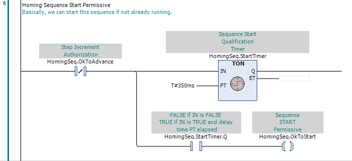
We next consider conditions that should prevent the Carrier Homing sequence from starting, but as of now cannot identify any condition other than that the sequence is already running. We establish HomingSeq.OkToStart to inhibit sequence activation while the sequence is running and provide a suitable delay between cycles to prevent unintended re-entry.
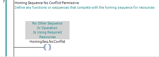
We next consider HomingSeq.NoConflict. Since this is the first sequence we have declared, we examine the existing workstation functions for any operations that might conflict with homing. We currently identify none, so we establish HomingSeq.NoConflict as TRUE. We will revisit this permissive as additional workstation functions are developed.
The Manual Mode HMI already includes a HOMING CYCLE pushbutton for requesting carrier homing. We declare HomePressed as a BOOL in GVL_HMI to carry this operator request into the control program.
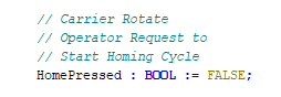
We begin developing HomingSeq.Trigger with the operator's request from the Manual Mode HMI. The other anticipated initiation path will be a handshake from the Normal Rotation Sequence when interrupted rotation requires homing.
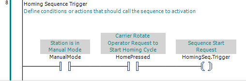
We establish activation of the Carrier Homing sequence using the permissives and trigger developed above. When the activation conditions are satisfied, we SET HomingSeq.OkToAdvance and HomingSeq.Active, allowing the sequence to begin executing its steps.
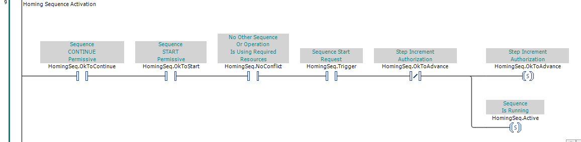
We now have the initial permissives, trigger, and activation logic established for the Carrier Homing sequence. Our readiness checks determine whether the required resources are available, while the starting permissives, conflict check, and trigger govern sequence initiation. When these conditions are satisfied, our activation logic SETs HomingSeq.Active and HomingSeq.OkToAdvance, establishing the sequence as active and ready to execute its steps.
Sequence Steps
With the sequence activation logic established, we turn our attention to developing the individual steps of the Carrier Homing sequence. As we consider what the first step must accomplish, we recognize an oversight in our starting permissives: nothing currently prevents homing from starting while the carrier is rotating. We need to correct this before proceeding.
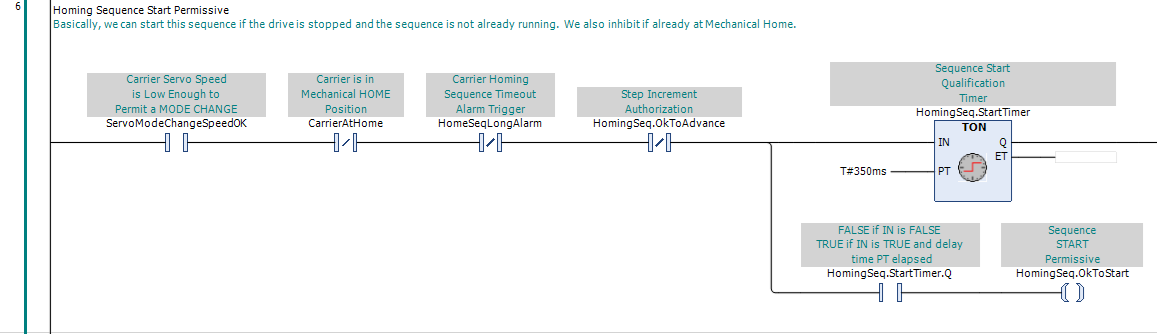
We return to HomingSeq.OkToStart and add ServoModeChangeSpeedOK as a required starting condition. This prevents the homing sequence from starting until the servo drive confirms that its speed is low enough to permit an operating-mode change. Because of how we set the limit in the drive, this can be interpreted as "the drive is stopped".
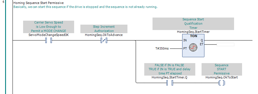
Having dealt with the overlooked starting condition, we return to developing the Carrier Homing sequence. Our first task is to establish the Carrier Rotate servo drive's Profile Velocity Operating Mode. This will allow us to control the carrier's rotational speed while searching for the registration target.
We declare HomeStep_01 in GVL_SequenceSteps, assigning it to bit 1 of HomeSeqSteps. This gives the first sequence step its own BOOL and descriptive comments, following the step-memory convention established during Sequence Preparation.
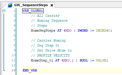
The first step in the Carrier Homing sequence is to set the servo drive to Profile Velocity Operating Mode. We SET HomeStep_01 when HomingSeq.OkToContinue and HomingSeq.OkToAdvance are TRUE. As with every sequence step, we only SET the step bit if it is not already TRUE.
We also consider how we will recognize completion of Step 1. Since this step requests the servo drive's Profile Velocity Operating Mode, we expect confirmation through DriveInVelocityMode. Until that confirmation is received, the HMI message indicates that we are waiting for the requested operating mode to be established.
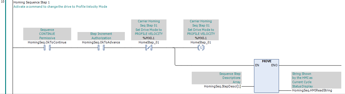
We now need to provide the actual text for HomingSeq.StepDescr[1]. In programming environments where string values can be edited directly in memory, this is straightforward. In CODESYS, however, we cannot simply open the array and type in the description. We need another way to assign the string.
Our options are less than appealing. We can return to the variable declarations and initialize the array with the desired strings, or develop additional Ladder logic to populate those strings. Either approach adds work and maintenance complexity.
Fortunately, CODESYS provides a much simpler alternative. We can enter the desired string literal directly into the MOVE instruction, eliminating the need to populate an intermediate array. This also makes the HMI message visible alongside the Ladder logic that uses it.
We replace the array reference in our Step 1 MOVE instruction with the desired string literal. The instruction now writes the message directly to HomingSeq.HMIReadString, without requiring an intermediate storage location.
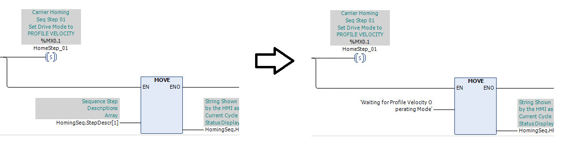
Since we can now provide the HMI status messages directly in our Ladder logic, the StepDescr array serves no useful purpose. We remove it from the AutoSequence structure, retaining HMIReadString as the destination for the current sequence status message.
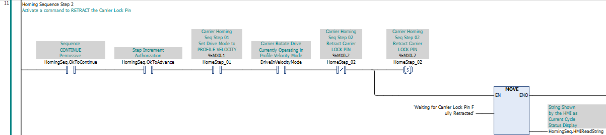
We declare HomeStep_02 in GVL_SequenceSteps. This step will request retraction of the Carrier Lock Pin. We SET this step when HomeStep_01 is TRUE and DriveInVelocityMode confirms that the servo drive has entered Profile Velocity Operating Mode.
We determine that Step 2 is complete when the Carrier Lock Pin is confirmed fully retracted. We will use Input011 to establish this condition, and provide an HMI message indicating that we are waiting for the pin to reach its fully retracted position.
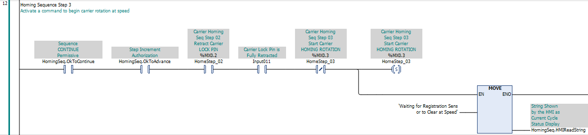
For the next step, we declare HomeStep_03 in GVL_SequenceSteps. This step requests rotation of the carrier at the homing speed. We SET HomeStep_03 when HomeStep_02 is TRUE and Input011 confirms that the Carrier Lock Pin is fully retracted.
The registration sensor may already be detecting a target when we issue the rotate command. Since the carrier could be anywhere within the target's detection range, we cannot assume that this indicates the correct stopping position. We therefore require the registration sensor to be clear and the servo drive to have reached its commanded homing speed before advancing to the next step, ensuring that the next registration target is detected while the carrier is rotating at the intended speed.
As we consider the next step of the Carrier Homing sequence, we recognize another condition worth addressing. If we get a request to home the turntable when the Carrier Lock Pin is fully extended and the registration sensor detects a target, the carrier is already mechanically HOME. Retracting the pin and rotating the carrier to find a position it already occupies would serve no useful purpose.
We recognize that establishing the carrier's mechanical HOME position and resetting the servo drive's position reference are two different operations. We therefore plan a separate Position Reset sequence that establishes the drive's position reference as zero each time mechanical HOME is confirmed. This sequence will also be used following normal carrier rotation, allowing us to maintain an accurate position reference without unnecessarily repeating the mechanical homing operation.
To recognize when mechanical homing is unnecessary, we need a common indication that the carrier is already HOME. We establish this indication in ModelessFunctions, making it available throughout the control program.

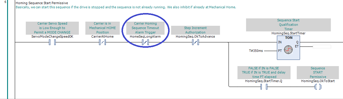
With CarrierAtHome established, we return to HomingSeq.OkToStart and add a normally closed contact to prevent the homing sequence from starting when the carrier is already mechanically HOME. The remaining starting conditions are unchanged.
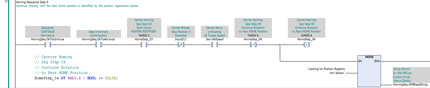
Until now, each step in our sequence has been an Actionable Step, directing the control program to perform an equipment action. However, not every sequence step needs to issue a command. Some steps simply record that the process has reached a significant point in its progression. We refer to these as Milestone Steps. A Milestone Step issues no equipment commands; it records progress and changes the qualifications for advancing to a subsequent step.
The next step in the Carrier Homing sequence is a Milestone Step that establishes when we are authorized to stop the carrier. We declare HomeStep_04 in GVL_SequenceSteps and SET it when the registration sensor is clear and the servo drive has reached the commanded homing speed. This step issues no equipment commands.
We determine that Step 4 is complete when the registration sensor detects the next target. Because the sensor was clear when we entered this step, the detection identifies a newly encountered target. We provide an HMI message indicating that we are waiting for the registration sensor to detect that target.
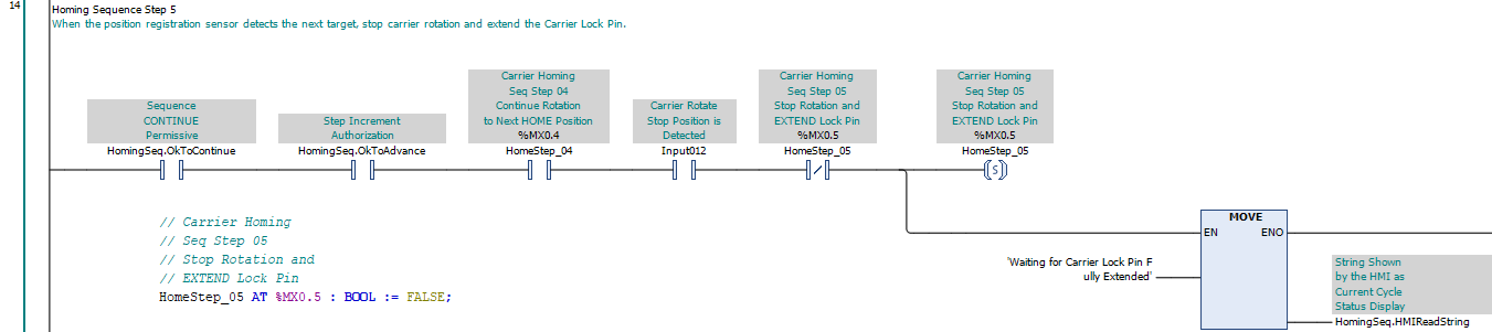
For the next step, we declare HomeStep_05 in GVL_SequenceSteps. This step stops carrier rotation and commands the Carrier Lock Pin to extend. We SET HomeStep_05 when HomeStep_04 is TRUE and the registration sensor detects the next target.
We determine that Step 5 is complete when the carrier has stopped rotating and the Carrier Lock Pin is confirmed fully extended. The fully extended indication confirms that the pin has engaged its mechanical locking position. Until both conditions are satisfied, the HMI indicates that we are waiting for the carrier to reach its mechanical HOME position.
The next rung registers the successful completion of the Carrier Homing sequence. We set HomingSeq.NormalDone when HomeStep_05 is TRUE and CarrierAtHome confirms that the carrier has stopped, the Carrier Lock Pin is fully extended, and the registration target is detected. At this point, mechanical homing is complete.
With mechanical homing complete, we declare HomeSeqPosResetReq in GVL_General and SET it to initiate a handshake with the Position Reset sequence. This requests the next operation, which will establish the servo drive's current position as zero.
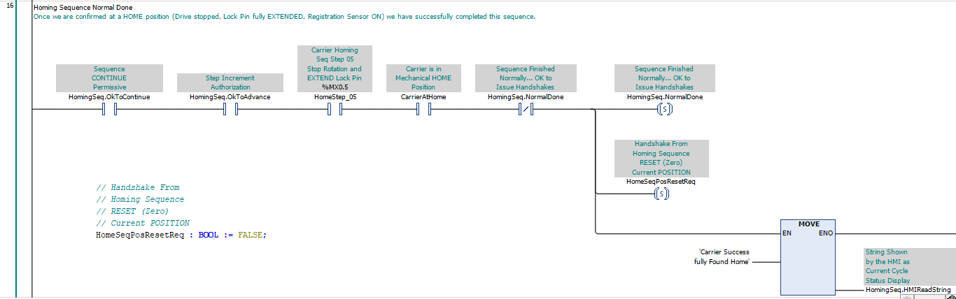
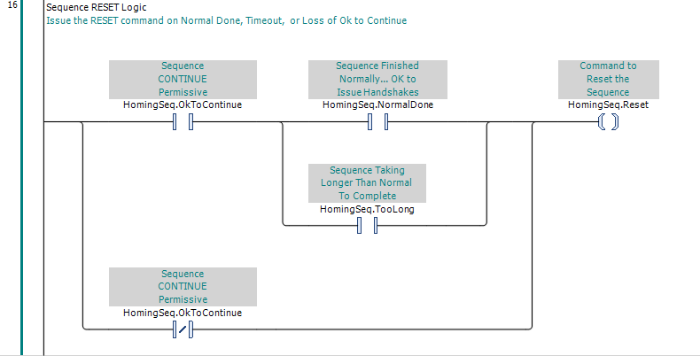
The next rung establishes the RESET conditions for the Carrier Homing sequence. The first condition is straightforward. When HomingSeq.NormalDone is TRUE, mechanical homing has completed successfully, and we reset the sequence to prepare for another request.
The second condition requires some consideration. One of the strengths of PLC Pro Sequencing is its ability to preserve sequence progress through interruptions, allowing an operation to resume when conditions permit. A sequence timeout does not necessarily require a reset. However, if our Carrier Homing sequence exceeds its allowed completion time, we consider the homing attempt unsuccessful. Since this sequence can start from anywhere, rather than preserve the sequence for recovery, we choose to abandon the attempt and reset it when HomingSeq.TooLong becomes TRUE.
We make the same decision regarding loss of HomingSeq.OkToContinue. Although PLC Pro Sequencing can support recovery following the loss of operating permissives, even through a power interruption, we have no need for that capability in this application. If the conditions required for continued homing are lost, we abandon the attempt and reset the sequence. The equipment-command logic below will need to provide the appropriate stopping response; asserting HomingSeq.Reset does not itself stop the servo drive.
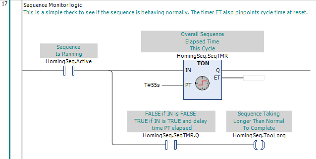
We monitor the overall execution time of the Carrier Homing sequence using HomingSeq.SeqTMR, which runs while HomingSeq.Active is TRUE. If the sequence exceeds the allowed execution time, the timer asserts HomingSeq.TooLong. Notice that this rung executes before the sequence reset actions. Even when a reset is requested, the timer continues to hold its elapsed time until it executes again with its input FALSE. This gives us an opportunity to capture the actual sequence execution time before it is cleared.
At this stage of commissioning, we deliberately use an artificially high timeout value. We do not yet have actual execution-time data on which to base a meaningful limit. After running the Carrier Homing sequence several times, we can evaluate its normal execution time and establish a more appropriate timeout that accommodates normal variation while detecting abnormal delays.
Because we will also need to issue an alarm on timeout, we add a rung just below the timer that sets a HomeSeqLongAlarm bit. We declare this bit in GVL_HMI and give it an eight-second timeout. This allows us to publish the alarm without interfering with normal sequence progression.
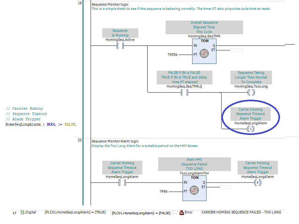
We also want to prevent another homing attempt from starting immediately after a sequence timeout. We return to HomingSeq.OkToStart and add a normally closed HomeSeqLongAlarm contact. This prevents another attempt during the eight-second alarm timeout, giving the operator an opportunity to recognize and react to the alarm condition.
Well, this is embarrassing. We've spent considerable time developing our Carrier Homing sequence, and we've overlooked two obvious requirements. Before rotating anything, we need to raise the Carrier Feed Stop to keep an inbound carrier from crashing into the turntable, and then raise the Carrier Lift to keep from binding up on the conveyor rails. Discovering this oversight after developing five sequence steps is frustrating, particularly because the omission should have been obvious from the beginning. Nevertheless, the correction is necessary. We need to insert two new steps at the beginning of our sequence and renumber the five steps we've already developed.
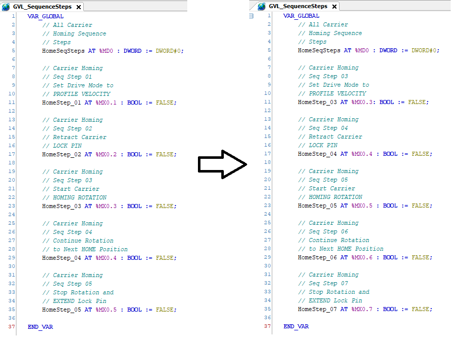
Fortunately, we don't need to discard the sequence logic we've already developed. We can preserve the existing five steps by moving each forward two positions in the sequence. Step 1 becomes Step 3, Step 2 becomes Step 4, and so on, with Step 5 becoming Step 7. We begin in GVL_SequenceSteps, where we revise the existing declarations. Once the declarations are updated, we can work through the Ladder logic, updating the step references in the existing logic. Then we can add the two missing steps and incorporate the new Step 2 completion condition into the revised Step 3.
The comparison below shows our original step declarations alongside the revised declarations. Notice that we change the variable names, memory addresses, and descriptions to reflect the new step numbers. We preserve the relationship between each step number and its corresponding bit in HomeSeqSteps, leaving the first two step positions available for the operations we need to add.
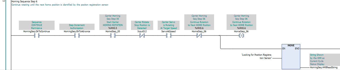
The revised Step 6 rung illustrates the changes required throughout our existing Ladder logic. We change the preceding step reference from HomeStep_03 to HomeStep_05, and both references to HomeStep_04 become HomeStep_06. The contact and coil descriptions already reflect the changes made to our declarations. We also update the rung title and comment to reflect the new step number. The conditions that establish the step and the HMI message remain unchanged. We apply the same approach to the remaining rungs that reference our renumbered steps.
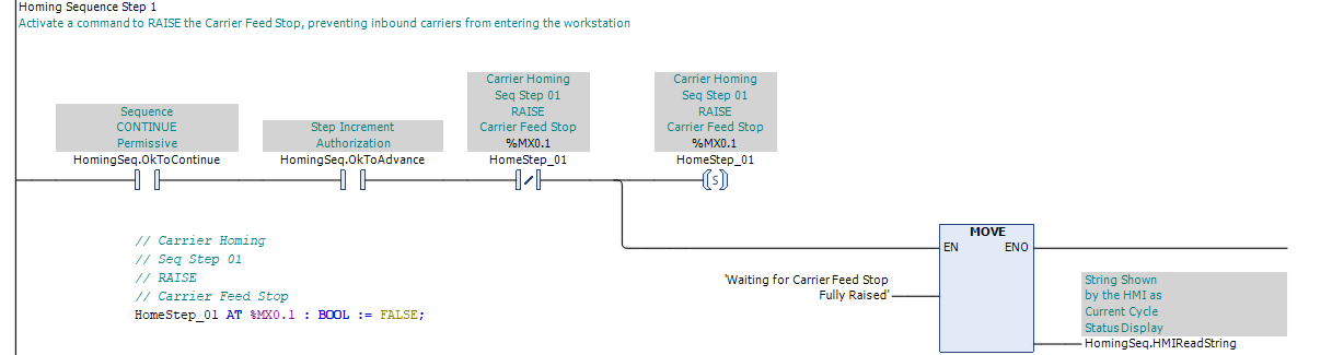
We begin our revised Carrier Homing sequence by raising the Carrier Feed Stop to prevent an inbound carrier from entering the turntable during homing. We declare HomeStep_01 in GVL_SequenceSteps. Since this is the first step, it requires no preceding step completion and begins with activation of the sequence.
We consider Step 1 complete when the Carrier Feed Stop is confirmed fully raised. This confirmation permits us to advance to Step 2, where we raise the Carrier Lift. Until then, the HMI indicates that we are waiting for the Carrier Feed Stop to reach its raised position.
With the Carrier Feed Stop confirmed raised, we can raise the Carrier Lift to provide the clearance needed for carrier rotation. We identify this operation as HomeStep_02, declared in GVL_SequenceSteps.
We have no sensor confirming that the Carrier Feed Stop is fully raised. Instead, we verify that its lowering solenoid is deenergized and that the stop is no longer detected in its fully lowered position. With the spring return raising the stop, these two conditions provide our best available confirmation that it is okay to proceed.
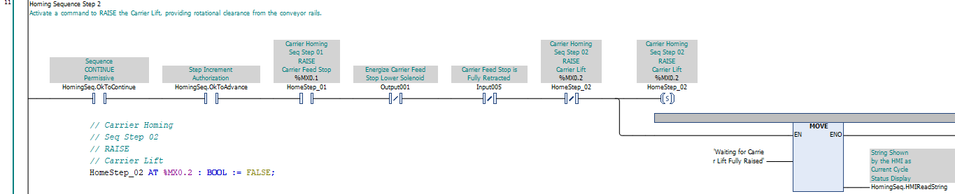
Finally, we revise the HomeStep_03 rung to require that HomeStep_02 is active and Input008 confirms the Carrier Lift is fully raised. This completes the integration of our two new preparation steps into the existing Carrier Homing sequence.
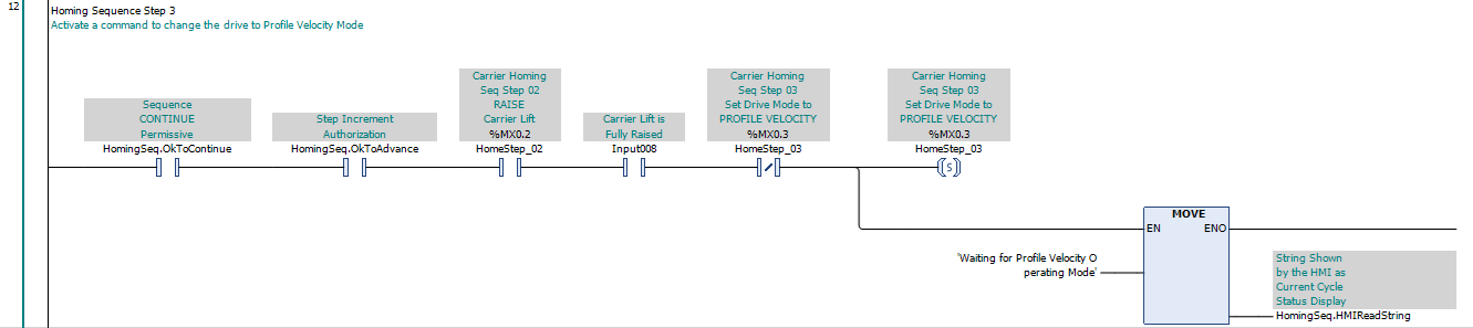
With our revisions complete, let's review the seven steps of the Carrier Homing sequence:
- Step 1: Raise the Carrier Feed Stop to prevent another carrier from entering the turntable.
- Step 2: Raise the Carrier Lift to provide clearance for rotation.
- Step 3: Establish Profile Velocity Operating Mode in the servo drive.
- Step 4: Retract the Carrier Lock Pin to release the carrier for rotation.
- Step 5: Begin Homing Rotation at the commanded homing speed.
- Step 6: Continue Rotation toward the next HOME position after confirming the registration sensor is clear and the servo is at speed.
- Step 7: Stop Rotation and Extend the Carrier Lock Pin when the next registration target is detected.
Once the carrier is confirmed mechanically HOME, HomingSeq.NormalDone registers successful completion of the sequence.
We've covered a lot of ground developing our Carrier Homing sequence. We've established the sequence steps, discovered and corrected two missing operations, revised our existing Ladder logic, established the Normal Done and Reset conditions, and added the Taking Too Long timer. That's considerable progress, but we're not finished yet. We now turn our attention to linking the sequence steps to the equipment commands that carry out the required operations.
Link Sequence Steps to Outputs
We use our sequence steps to guide the development of the equipment-command logic. Starting with HomeStep_01, we know that our first requirement is to raise the Carrier Feed Stop. We therefore examine the existing output-control logic to determine how we can accomplish this operation.
Our first step requires us to raise the Carrier Feed Stop. Since the stop is spring-returned to its raised position, we accomplish this by deenergizing its lowering solenoid.
There is, however, a complication. Our homing sequence can operate while the workstation remains in Manual Mode, where an operator can still request that the stop be lowered through the HMI. We certainly don't want that happening during homing. We therefore add a normally closed HomingSeq.Active contact to the existing Manual Mode LOWER command rung, preventing new LOWER commands while the sequence is running.
There is another possibility to consider. The Manual Mode LOWER command might already be established when the homing sequence starts. Although our sequence can inhibit the physical output, that existing command could become effective again when the sequence resets. We therefore add HomingSeq.Active to the Manual Mode RESET rung, clearing any previously established LOWER command when homing begins.
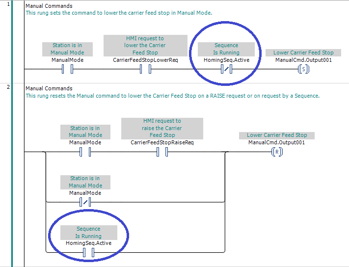
We have no reason to inhibit the HMI RAISE command. The Carrier Feed Stop must remain raised throughout homing, so an operator requesting the same action creates no conflict. We can freely share control of this operation with the HMI because both commands produce the same result. Only conflicting commands require our attention.
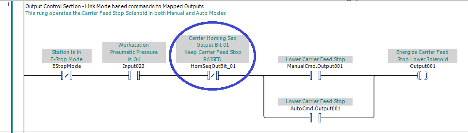
We next establish the command that keeps the Carrier Feed Stop raised during homing. We declare HomSeqOutBit_01 in GVL_SequenceSteps and energize it while Step 1 is established and the sequence is permitted to continue. We will use this bit to inhibit the Carrier Feed Stop LOWER output.
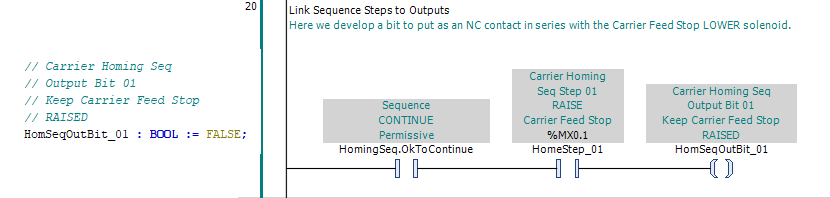
We then use HomSeqOutBit_01 in the existing OutControl rung for the Carrier Feed Stop. We place its normally closed contact ahead of the Manual and Auto LOWER command branches. When the bit is TRUE, neither command can energize the lowering solenoid, allowing the spring to maintain the Carrier Feed Stop in its raised position. When the bit becomes FALSE, normal output control is restored.
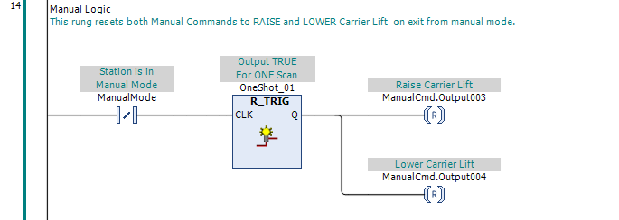
Examining the Carrier Lift output logic raises another concern. A Manual Mode RAISE or LOWER command might remain set when we leave Manual Mode, potentially causing motion when we re-enter Manual Mode. Fortunately, the Carrier Lift uses a detented valve, which retains its selected position when both solenoids are deenergized. We therefore use a one-shot on exit from Manual Mode to RESET both Manual Carrier Lift commands, preventing those commands from creating a problem during mode changes.
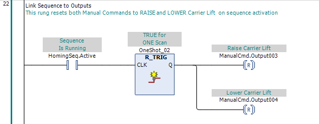
There is another situation to consider. Our Carrier Homing sequence can start while the workstation remains in Manual Mode, so our previous mode-exit logic does not execute. Either Carrier Lift Manual command might already be established when the sequence starts. We therefore use a rising-edge one-shot on HomingSeq.Active to RESET both Manual Carrier Lift commands when the sequence becomes active, before the output-control logic executes.
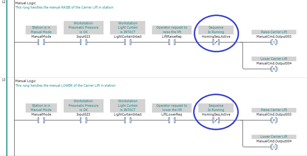
Resetting the existing Manual Carrier Lift commands when the homing sequence starts addresses only part of the problem. Since the workstation remains in Manual Mode, the operator can still request RAISE or LOWER through the HMI. We therefore add normally closed HomingSeq.Active contacts to both Manual command rungs, preventing either command from being established while the homing sequence is running.
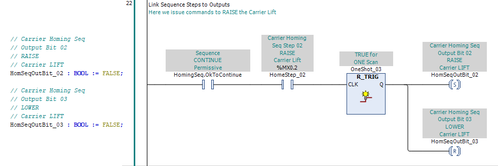
We now establish the sequence commands for raising the Carrier Lift. We declare HomSeqOutBit_02 for RAISE and HomSeqOutBit_03 for LOWER in GVL_SequenceSteps. When HomeStep_02 is established and the homing sequence is permitted to continue, a rising-edge one-shot SETs the RAISE command and RESETs the LOWER command. The RAISE command remains latched until we explicitly RESET it.
We next incorporate the Carrier Homing sequence commands into the existing OutControl logic for the Carrier Lift. We add HomSeqOutBit_02 as another RAISE command for Output003, and HomSeqOutBit_03 as another LOWER command for Output004. Both rungs retain their E-Stop inhibition, but we replace the individual command-bit interlocks with interlocks based on the opposing physical output.
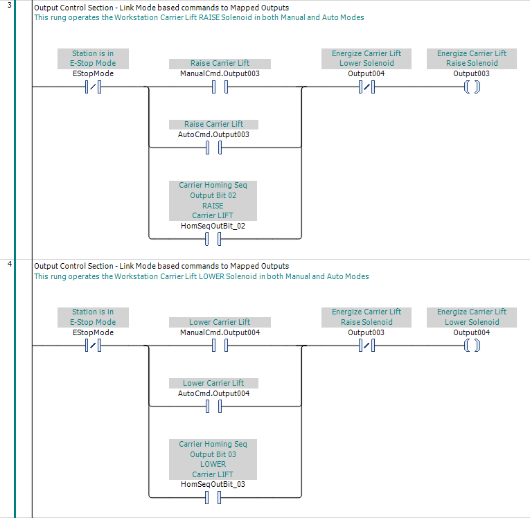
As we incorporated the homing sequence commands into the Carrier Lift output logic, we saw an opportunity to simplify our approach. Rather than preventing conflicting RAISE and LOWER commands within each operating mode or sequence, we recognized that the actual requirement is to prevent both solenoids from being energized simultaneously. We therefore moved the interlocking to the physical output-control logic, using the state of Output004 to inhibit Output003, and vice versa. This protects against conflicting commands regardless of their source, without requiring us to manage every possible conflict between command bits.
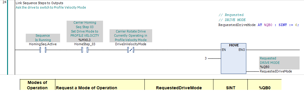
As we develop the operating-mode request logic, we examine the DriveMode variable previously declared in GVL_IO. Its name is potentially misleading, as it could be interpreted as indicating the servo drive's current operating mode. In reality, this variable carries our REQUESTED operating mode to the drive through EtherCAT. To make its purpose clear, we rename it RequestedDriveMode and update the IO Schedule accordingly. The existing address, datatype, and initial value remain unchanged.
Moving on to HomeStep_03, we need to set the proper mode (Profile Velocity) for the Carrier Rotate servo drive. The existing DriveInVelocityMode bit is TRUE when the drive is operating in this mode. While the sequence is Active, HomeStep_03 is established, and the drive is not operating in our desired mode, we use a MOVE instruction to write a value of 3 to RequestedDriveMode, requesting a change to Profile Velocity Operating Mode. Once the drive confirms that mode, the MOVE instruction is disabled.
Next, we turn to the Carrier Lock Pin, which must retract during HomeStep_04 to permit carrier rotation. As with the Carrier Feed Stop, we need to prevent Manual Mode commands from interfering with the homing sequence. We therefore add normally closed HomingSeq.Active contacts to the existing Manual RETRACT and EXTEND request logic, preventing the operator from issuing either command while homing is active. The existing RESET conditions for leaving Manual Mode and losing pneumatic pressure remain unchanged.
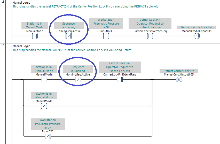
Inhibiting new Manual RETRACT commands does not address commands that are already established when the homing sequence starts. We therefore add a normally open HomingSeq.Active contact as another RESET condition for ManualCmd.Output005. This keeps the Manual RETRACT command cleared throughout homing, preventing it from interfering with the sequence's control of the Carrier Lock Pin.
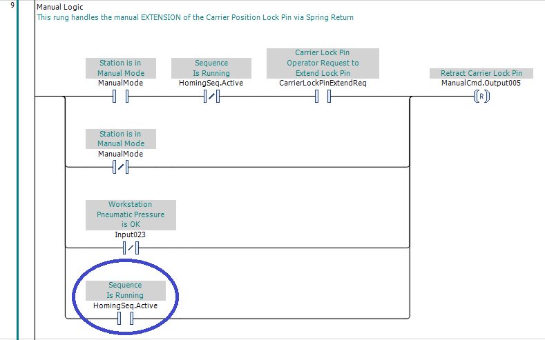
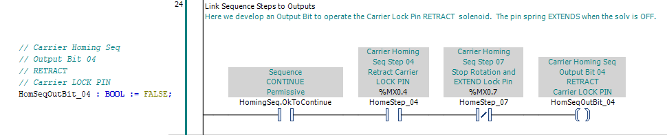
Having dealt with potentially conflicting Manual commands, we next create the sequence output command for retracting the Carrier Lock Pin. We declare HomSeqOutBit_04 in GVL_SequenceSteps and energize it from HomeStep_04 until HomeStep_07 begins. When the solenoid deenergizes, the spring-return valve extends the Carrier Lock Pin.
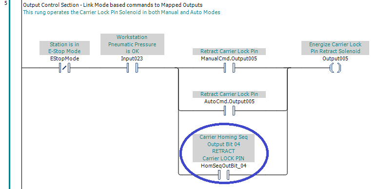
With HomSeqOutBit_04 programmed, we add it to the existing OutControl rung for Output005. We place the homing sequence RETRACT command in parallel with the existing Manual and Auto commands. The E-Stop and pneumatic-pressure conditions continue to qualify the output.
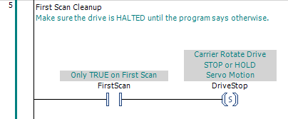
As we approach the point in commissioning when we first apply power to the Carrier Rotate servo drive, we recognize what could be an unpleasant surprise. We've initialized the drive for Profile Velocity Operating Mode with a target speed of 3000, but in Velocity mode you don't tell the drive to run... you tell it to HALT. Once enabled, the drive could begin rotating without any request from our sequence logic. That would certainly make commissioning interesting! To prevent this, we add a rung to our existing Startup program that SETs DriveStop during the first PLC scan. This asserts the servo drive's HALT command, which remains active until our control program deliberately releases it.
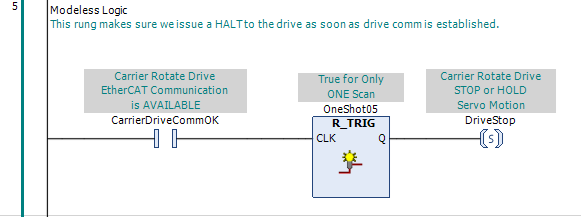
On another front, although we SET DriveStop during the first PLC scan, communications with the servo drive may not yet be established. More importantly, communications could be lost and restored after the control program has released HALT to permit rotation. We therefore add a one-shot in ModelessFunctions that SETs DriveStop whenever CarrierDriveCommOK transitions from FALSE to TRUE. This ensures that we request HALT each time communications with the drive become operational.
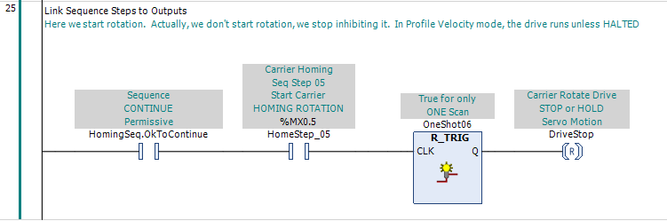
Now that we have our foot on the brakes, we can start the car. Back to Step 5 of our sequence, where we will command the drive to rotate. We currently have RotateTargetSpeed initialized to 3000, which we expect to provide a suitably slow speed for homing. When HomeStep_05 is established and the sequence is permitted to continue, we use a rising-edge one-shot to RESET DriveStop, releasing HALT and allowing the drive to begin rotating. The one-shot prevents this step from repeatedly releasing HALT when a subsequent step commands the drive to stop.
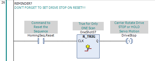
Having just released HALT to begin rotation, we recognize another important requirement. What happens if the homing sequence is interrupted before we stop rotation? We know from PLC Pro Sequencing that we'll eventually program the sequence RESET actions. Although we're not ready to develop that logic, we don't want to overlook something as important as stopping the servo drive. We therefore add a rung now that SETs DriveStop when HomingSeq.Reset occurs, ensuring that we address this requirement while it is fresh in our minds.
With the servo drive at target speed and the registration photoeye clear, we reach another milestone in our homing sequence. We advance to Step 6 without issuing any new commands. The carrier continues rotating while we watch for the next registration target. Not every sequence step requires an action. Sometimes reaching a particular condition is all we need to establish before moving on.
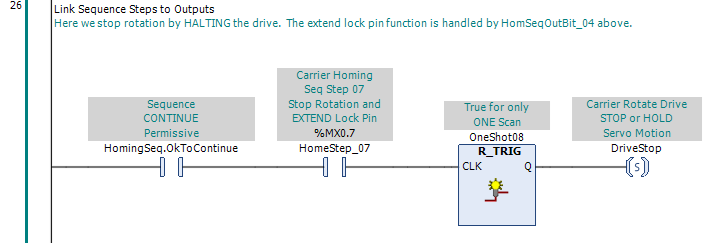
When the registration photoeye detects the next target, the homing sequence advances to Step 7. We use another rising-edge one-shot to SET DriveStop, asserting HALT and commanding the servo drive to stop rotating. The Carrier Lock Pin retract command is already handled by HomSeqOutBit_04, which becomes FALSE when Step 7 is reached, allowing the pin to extend. Together, these actions bring the carrier to its mechanical HOME position.
With the servo drive commanded to HALT at Step 7, we've completed the output-control logic for our Carrier Homing sequence. We've established the commands needed to prepare the workstation, control carrier rotation, and return the Carrier Lock Pin to its extended position. We've also addressed potential conflicts with Manual Mode commands and ensured that an interrupted sequence requests HALT. All that remains is to program what happens when we get the instruction above to RESET the homing sequence.
Sequence RESET
We now complete the Carrier Homing sequence by developing its RESET logic. We've already established the conditions that assert HomingSeq.Reset, and earlier we added a rung to ensure that RESET commands the servo drive to HALT. Here we bring those actions together with the remaining RESET requirements. We clear the sequence's Active, OkToAdvance, and NormalDone bits, MOVE zero into the sequence step register, and restore the HMI status message to indicate that the homing sequence is IDLE.
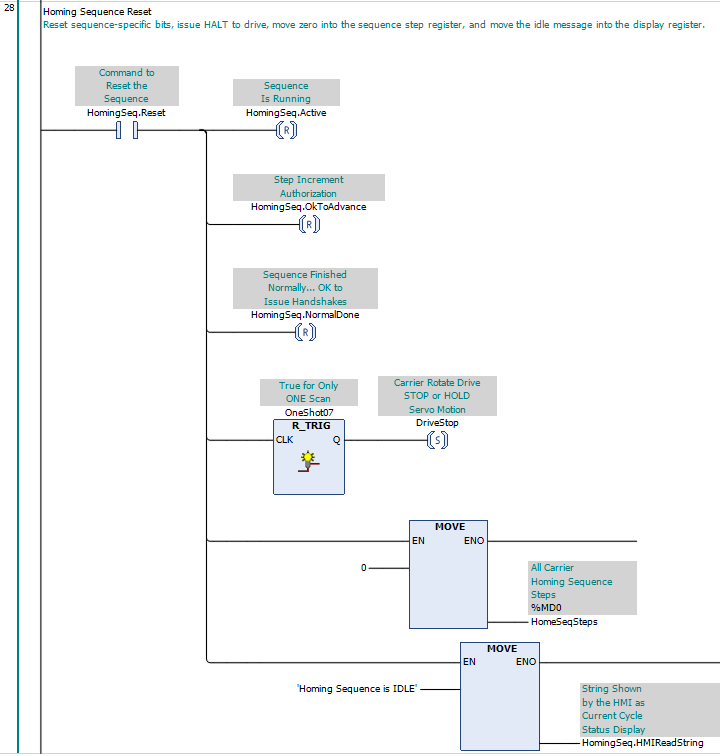
Resetting the HMI status message to IDLE reminds us that the message also needs to be initialized when the PLC first starts. Otherwise, the HMI may display an empty string until the homing sequence executes for the first time. We therefore return to our existing Startup program and add a MOVE instruction that establishes the same Homing Sequence is IDLE message during the first PLC scan.
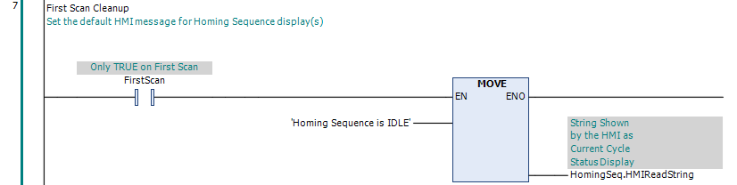
With the RESET logic and first-scan HMI initialization established, we complete the Carrier Homing sequence programming. Our control program builds without errors, and we're ready to move on.
We spend the next several hours testing the homing sequence and adjusting the servo drive parameters to achieve smooth, predictable operation. We experiment with acceleration, deceleration, and target speed until the carrier rotates at a reasonable pace, decelerates smoothly when HALT is commanded, and allows the Carrier Lock Pin to engage without excessive mechanical shock. We also test sequence interruptions, RESET behavior, and recovery to ensure the equipment responds as intended. Once we're satisfied with the results, we retain the optimized drive settings and consider the homing sequence ready for service.
Notice that RESET does not command the Carrier Lift to lower. We're still processing, and establishing mechanical HOME is only part of the job. You may remember that we issued a Handshake to call our next sequence, Position Reset. More on that on the next page.
If you made it this far in the tutorial, sweet. You now have worked with us through your first actual PLC Pro sequence. And this one is complex, because it is happening in Manual Mode. Normally when we commission a drive we are in Manual Mode, putting together jog functions on a relatively static drive. This one has internal mode changes and will essentially speak two different languages depending on what we are asking it to do. In any event, thanks for staying with it, and we will see you in the next sequence.