Purpose
In PLC Pro Sequencing, Sequence Reset answers one basic question: “What must we do to reset this sequence?”
The Sequence Reset logic is programmed as the final section at the bottom of each PLC Pro Sequence's ladder.
Sequence Reset performs the actions required to reset a PLC Pro Sequence.
Place Sequence Reset Last
Sequence Reset is programmed as the final section at the bottom of each PLC Pro Sequence's ladder. The conditions that assert Sequence Reset are established earlier in the sequence programming, leaving this final section to actually perform the reset actions.
This placement provides a practical advantage when Link Sequence to Outputs contains latched machine-function calls. Logic required to reset one of those calls when the sequence resets can remain in close proximity to the logic that controls the latch.
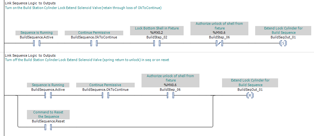
In Figure 1, the call to extend the lock cylinder is SET by the normal sequence conditions on the upper rung. It is RESET on the lower rung, either when Step 6 is established or on the single scan when Reset is TRUE. Because the actual Sequence Reset section is programmed below these rungs, the reset path can act on the latched call before the sequence-control state is cleared. The same ordering principle can be applied to adjacent RESET/SET rung pairs when the required latch behavior is reversed.
Perform the Sequence Reset Actions
When Sequence Reset is TRUE, the logic in this section performs the actions required to reset the PLC Pro Sequence. This will likely include recording cycle-related information, clearing the sequence-control and Sequence Step bits, and handling any output conditions that might need attention as the sequence returns to idle.
The Sequence Reset actions must be arranged in the order required by the application. Any action that depends on the existing sequence state must occur before the reset logic clears the state on which that action depends.
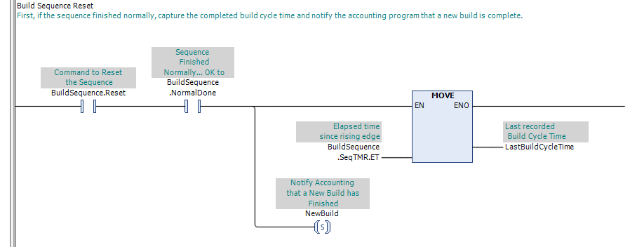
In Figure 2, Sequence Reset and Normal Done qualify the actions associated with a normally completed cycle. The elapsed sequence time is recorded in LastBuildCycleTime, and NewBuild is SET to notify the accounting logic that another build has been completed. These actions occur before the sequence-control state is cleared so the information from the completed cycle is still available.
Because Sequence Reset may also be asserted following an abnormal or deliberately requested reset, Normal Done can be used to distinguish a normally completed cycle from other reset conditions. Any actions that depend on that distinction must occur before the sequence-control state is cleared, because Normal Done itself is about to be reset.
For a normally completed cycle, actions such as recording the cycle time or establishing a NewBuild handshake, as in Figure 2 above, may be performed when Normal Done becomes TRUE or during Sequence Reset, largely as a matter of programmer preference.
Information from an abnormally ended cycle must be captured during Sequence Reset, because Normal Done is never established.
The cycle-related actions shown in Figure 2 are only examples. An application may also use completed-cycle information to perform calculations, such as maintaining a rolling average of normal cycle times. That information is often used to establish a realistic value for the Too Long timer.
Completed-cycle information can also be useful for production analysis. For example, cycle-time records associated with individual operators can be used to evaluate the effect that a specific operator has on average cycle time. Cycle-time drift or other performance changes reflected in those records can then be identified and addressed.
After any actions that depend on the existing sequence state have been completed, the sequence-control and Sequence Step bits can be cleared.
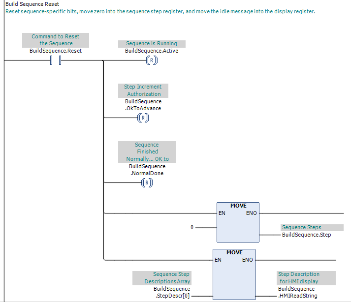
In Figure 3, Sequence Reset resets Sequence Active, OK to Advance, and Normal Done. Zero is then moved into the Sequence Step register to clear all established steps, and the idle step description is moved into the HMI display string.
Where a sequence status display is provided, Sequence Reset also restores the message associated with the idle state. This keeps the displayed Sequence Step description consistent with the actual sequence state after the sequence-control and step bits have been cleared.
Once Sequence Reset is TRUE, the sequence-control and Sequence Step bits must be allowed to clear. Conditions such as OK to Continue, mode status, permissives, faults, or the current Sequence Step are never allowed to prevent the sequence from returning to idle.
Sequence Reset does not change handshake bits. A handshake established when Normal Done becomes TRUE, or at any other point in the sequence, remains available until the receiving logic or another deliberately defined condition clears it.
The actions performed during Sequence Reset must be completed during the scan in which Sequence Reset is TRUE. Any action that requires a response or confirmation over subsequent scans must be completed during normal sequence progression before the sequence is reset.
PLC Pro Design Rules
- The Reset Conditions logic determines when Sequence Reset is asserted.
- The Sequence Reset logic performs the actual reset actions.
- Place Sequence Reset rungs after Link Sequence to Outputs rungs.
- Perform any action that depends on the existing sequence state before clearing that state.
- Use Normal Done to distinguish normally completed cycles from other sequence resets.
- Explicitly reset all individually defined sequence-state Boolean values (ex: Sequence Active).
- When sequence-step bits are grouped into one register, clear them by writing a zero to that register.
- Where a screen is available, restore the HMI message showing the sequence as idle.
- Condition the rung(s) that clear the sequence state only with Sequence Reset.
- Sequence Reset does not clear handshake bits.
- Complete all Sequence Reset actions during the scan in which Sequence Reset is TRUE.
Diagnostics
Troubleshooting Sequence Reset is primarily a matter of confirming that the required reset actions were actually performed.
Sequence Reset is an event rather than a persistent state and will normally be TRUE for only one PLC scan. Because it is rarely observed directly, troubleshooting usually requires reconstructing what happened from the state left behind.