Purpose
In PLC Pro™ Sequencing, Link Sequence to Outputs answers one basic question: “What does this sequence ask the machine to do as it progresses?”
The Link Sequence to Outputs logic has a defined location after the Sequence Taking Too Long logic and before the actual Sequence Reset logic.
Each Sequence Step calls for a specific action to occur, and the Link Sequence to Outputs logic calls the machine functions needed to perform that action.
Those sequence-specific machine-function calls are normally used by the equipment-level logic that controls the requested machine functions rather than being mapped directly to physical output points.
Place Link Sequence to Outputs Before Sequence Reset
In each PLC Pro Sequence, the Link Sequence to Outputs logic is programmed after Sequence Taking Too Long and before the actual Sequence Reset logic.
This placement keeps the programming for latched sequence commands together. When a sequence command is latched, the logic that sets and resets that command should normally be kept in close proximity, often as a pair of adjacent rungs. Placing Link Sequence to Outputs before the actual Sequence Reset logic allows any required command reset associated with an abnormal sequence reset to remain with the logic that controls this command.
The consistent location also gives maintenance personnel a predictable place to find all machine-function calls originating from the sequence. From there, they can determine whether the sequence is making the expected call and trace that call through the equipment-level logic as necessary.
Call Machine Functions from Sequence Steps
Each Sequence Step calls for a specific action to occur. The Link Sequence to Outputs logic uses the established step states to call the machine functions needed to perform those actions.
Some machine-function calls are maintained from the Sequence Step that first calls for them until Sequence Active is reset at the end of the full sequence.
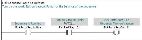
In Figure 2, PickParts_02 is the Sequence Step calling for the vacuum pump to be turned on. Because established Sequence Step bits remain TRUE as the sequence progresses, PickPartsSeqOut_01 remains asserted through all subsequent steps while Sequence Active remains TRUE. No later Sequence Step is used to turn this call off; it is intended to remain active for the balance of the sequence and drops when Sequence Reset clears Sequence Active.
Some machine-function calls are turned on by one Sequence Step and turned off by a later Sequence Step.

In Figure 3, BuildStep_05 is the Sequence Step that calls for screwdriving to begin, and the normally closed BuildStep_06 condition ends that call when the sequence advances to the next action. Because BuildStep_05 remains TRUE after it is established, BuildSeqOut_02 remains asserted throughout that interval.
For each machine-function call, the PLC Pro should deliberately determine whether OK to Continue should qualify that call. Some actions should stop when the sequence is placed on hold, while others may need to remain commanded through the interruption. In Figure 3, screwdriving is not permitted while the station is on hold, so OK to Continue is included as a condition of the call.
Some machine-function calls are latched by one Sequence Step and explicitly unlatched by a later Sequence Step.
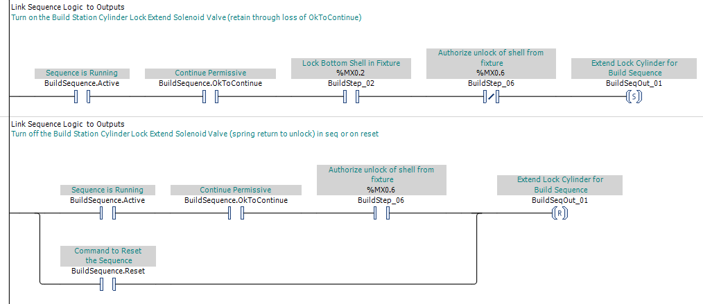
In Figure 4, BuildStep_02 is the Sequence Step that latches BuildSeqOut_01, and BuildStep_06 explicitly unlatches the call later in the sequence. Once BuildSeqOut_01 is latched, changes in the logic that originally asserted the SET rung do not clear the command. For example, OK to Continue may become FALSE after the command is set, while BuildSeqOut_01 remains established until one of its defined unlatch conditions becomes TRUE. Sequence Reset provides an additional unlatch path so that an abnormal reset does not leave the command in its set state.
Some machine-function calls are latched by a Sequence Step and intentionally left in that state when the programmer determines that this is likely the normal state for the output.
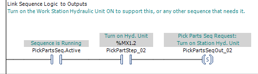
In Figure 5, PickPartStep_02 is the Sequence Step that latches PickPartsSeqOut_02, requesting that the workstation hydraulic unit be turned on. Once the request is latched, this sequence does not reset it when it progresses or completes. The hydraulic unit is left available to support this or other sequences that need it, and the machine logic responsible for the hydraulic unit determines when that established command should eventually be removed.
Some machine functions use a pair of opposing latched commands. When a Sequence Step latches one command, the Link Sequence to Outputs logic should also unlatch the opposing command.
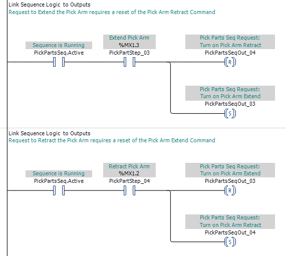
In Figure 6, PickPartStep_03 calls for the Pick Arm to extend. The logic resets PickPartsSeqOut_04, the retract call, and latches PickPartsSeqOut_03, the extend call. When PickPartStep_04 later calls for the Pick Arm to retract, the opposite occurs: the extend call is reset and the retract call is latched. This prevents both opposing latched commands from remaining established at the same time.
Route Sequence Calls Through Equipment-Level Logic
A machine-function call made in Link Sequence to Outputs is normally a sequence-specific internal command. It is passed to the equipment-level logic for that machine function rather than being mapped directly to a physical output.
At the equipment level, the sequence-specific call can be combined with calls for the same machine function from Manual Mode, other sequences, or other appropriate parts of the control program. These separate request sources all call the same equipment-level function.
The equipment-level logic also applies the permissives and other conditions that are common to the machine function regardless of which request source is calling for it. When an appropriate call is present and the required conditions are satisfied, the equipment-level command is established.
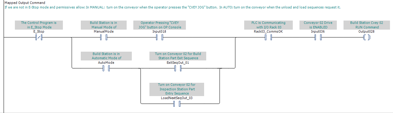
In Figure 7, the Build Station Conveyor 02 run command can be established from either Manual Mode or Auto Mode. In Manual Mode, the operator makes the call by pressing the "CVEY JOG" button. In Auto Mode, either the unload sequence or the load sequence can call for the conveyor to run. These request paths then share the conditions common to operation of the conveyor before its equipment-level run command is established.
In the output-mapping section of the program, that equipment-level command is mapped to the physical output address that operates the device. This preserves a consistent path from a sequence-specific call, through the common equipment-level logic, to the physical output.
PLC Pro Design Rules
- Place Link Sequence to Outputs after Sequence Taking Too Long and before the actual Sequence Reset logic.
- Use established Sequence Step states to call the machine functions required as the sequence progresses.
- Use continuously driven or latched behavior as appropriate for each machine-function call.
- For each machine-function call, deliberately determine whether OK to Continue should qualify the call.
- For every latched machine-function call, deliberately define where and how it is reset.
- When opposing machine-function calls are latched, establishing one should also reset the opposing call.
- Use sequence-specific internal commands for machine-function calls rather than directly controlling physical output points.
- Route sequence-specific calls through the common equipment-level logic.
- Map the resulting equipment-level command to the appropriate physical output.
Diagnostics
Once the current Sequence Step progression is understood, Link Sequence to Outputs answers the next troubleshooting question: “What is this sequence asking the machine to do?”
The sequence-specific machine-function calls provide a convenient place to verify whether the sequence is making the expected requests. If an expected call is not present, troubleshooting remains within the sequence logic.
If the expected sequence-specific call is present but the machine action is not occurring, follow that call through the equipment-level logic. Check the common permissives and other conditions, verify that the equipment-level command is established, and continue through the output mapping and field hardware as necessary.