Purpose
The programmatic E-Stop Mode response does not replace the Emergency Stop response or make the ordinary PLC part of the safety-related control system. It begins after the PLC detects that the safety-system response is in effect and remains subordinate to that response.
The purpose of the E-Stop Mode response is to place the ordinary control program in a defined and predictable condition whenever the safety system is enforcing the Emergency Stop response. The programmatic response must suspend ordinary machine operation, coordinate with the resulting installation behavior, and provide the information needed for correction and recovery.
Relationship to the Emergency Stop Response
When the PLC enters E-Stop Mode, the safety system and controls hardware are already executing the installation’s Emergency Stop response. The PLC Pro’s ordinary control program (the control program) must recognize that condition and coordinate its logic with the resulting state and/or actions of the installation.
Using PLC Pro Methods, when the PLC enters E-Stop Mode, the control program immediately cancels Auto Mode. See the Auto Mode discussion for additional information.
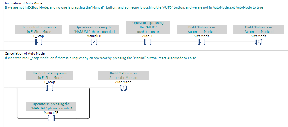
The control program must not treat E-Stop Mode as the command that creates the safe condition. Its role is to mirror the detected safety-system status, prevent ordinary control logic from interfering, and manage the non-safety-related program behavior that accompanies the Emergency Stop response.
The PLC Pro must account for the difference between removing power from an output and removing the program command that produced it. When the safety system de-energizes field devices, output commands may remain present in the control program and become effective again when the safety system is reset. Each command must therefore be cancelled, retained, inhibited, or reconciled according to the actuator behavior and the defined recovery process.
Pin stops used to arrest rolling pipe provide an example. A spring-return valve may be selected so loss of power extends a set of pin stops into the pipe path. The safety system produces that physical response by de-energizing the valve, but a retained retract command could become effective again when field power is restored. The control program must therefore cancel or inhibit that command during E-Stop Mode so resetting the safety system leaves the pin stops extended until a deliberate command retracts them.
Functions That Remain Active
The physical installation may not reach its final Emergency Stop condition immediately. Drives may be completing controlled stops, brakes may be applying in a defined sequence, pressure may be decaying, and equipment may still be moving under stored energy. The control program must account for this transition rather than assume that all motion has stopped and all hazardous energy has been removed as soon as E-Stop Mode is entered.
Diamond presses provide an extreme example. Some of these presses can concentrate over a million psi across a punch and die set. Immediately dumping the hydraulic pressure could cause the gasketing to fail and produce a violent decompression capable of damaging equipment and endangering personnel. On these presses, invocation of the Emergency Stop response initiates the normal controlled-decompression sequence, reducing the pressure gradually to zero. Because controlled decompression is required to prevent that hazardous release, its initiation and execution must be implemented as a safety-rated function of the press. This process could take more than an hour.
The control program must not issue commands that interrupt, override, or conflict with functions required by the Emergency Stop response. In practice, this often means resetting or inhibiting latched commands and other retained states so they do not cause unauthorized motion or other activity when the safety system is reset.
A safety PLC may execute some or all of these actions through validated safety-related application software. Those actions are part of the safety system and the Emergency Stop response. They are not part of the control program’s E-Stop Mode response.
Inhibit Ordinary Machine Operation
When the PLC enters E-Stop Mode, ordinary operator commands for machine operation must be ignored or inhibited. The control program must cancel Auto Mode, and ordinary control commands must not be allowed to initiate motion, energize working devices, or interfere with the Emergency Stop response.
Commands that were active before the Emergency Stop response was invoked must not remain effective merely because an HMI command, selector switch, sequence request, or other operating input remains present. The control program must require the appropriate recovery and operating conditions before those commands can again become effective.
Using PLC Pro Methods, when a maintained selector switch can command motion in Manual Mode, the control program uses an "Armed" qualifier to prevent the command from becoming effective immediately after safety-system reset. Entering E-Stop Mode resets the qualifier. After the safety system is reset, the switch must first be detected in its Off position before the control program rearms it. Only then can moving the switch to a commanded position initiate motion.
In many control programs, a not-E-Stop Mode condition is placed in series with ordinary actuator output commands so those commands cannot remain effective while the Emergency Stop response is in effect. This is one possible implementation, not a universal rule. The PLC Pro must determine how each command is handled so safety-system reset does not cause unauthorized motion or interfere with a function required by the Emergency Stop response.
Entering E-Stop Mode does not necessarily require every program state to be erased. Information needed for diagnostics, state reconciliation, or controlled recovery may be retained, but neither the retained state nor safety-system reset may resume machine operation. The control program must require a deliberate operator request before motion or other machine operation can resume.
Operator Indication and Diagnostics
HMI must clearly indicate whenever the PLC is in E-Stop Mode. The indication should distinguish that program mode from an ordinary stopped, paused, or idle condition so the operator understands that the safety-system response is in effect.
The PLC Pro Method is to provide HMI that identifies any devices, safety functions, or required conditions preventing safety-system reset. The displayed information should help the operator locate and correct every such condition.
The control program does not determine whether or when the safety system may be reset. It does, however, coordinate with HMI to fully inform maintenance and operations staff of any detected conditions that prevent reset.
The overall E-Stop indication via HMI must follow the detected safety-system status. Resetting an Emergency Stop device removes that device’s demand and, on some installations, may also reset the safety system. The HMI must continue to indicate E-Stop Mode until the control program detects that the safety system has been reset.
For example, an operator may reset one Emergency Stop pushbutton while another Emergency Stop device remains actuated, a guard remains open, or another required safety-system condition remains unsatisfied. The reset device no longer demands the Emergency Stop response, but the safety system remains unreset and HMI continues to indicate both E-Stop Mode and the underlying causes preventing reset.
Resetting an Emergency Stop device or the safety system is not a request to resume machine operation. Motion or other operation must require a separate, deliberate operator command.
On a simple machine, an Emergency Stop pushbutton may be the only device used to invoke the Emergency Stop response. Pulling or twisting the pushbutton back out is a deliberate operator command to reset that device and may permit the safety system to reset. The machine nevertheless remains stopped until the operator separately requests motion or automatic operation.
Implementation
Using PLC Pro Methods, the control program’s E-Stop Mode response is organized around the global "E-Stop" bit (see Figure 1). Whenever that bit is TRUE, the control program cancels Auto Mode, inhibits ordinary machine commands, and coordinates with functions that remain active as required by the safety-system design. It also supplies related status and diagnostic information to HMI.
Individual equipment modules, sequences, and operating modes should use the common E-Stop Mode status rather than independently interpreting safety-system inputs. This produces one consistent program-wide response to the Emergency Stop condition and avoids contradictory behavior between separate portions of the control program.
PLC Pro Design Rules
- The control program must recognize that the Emergency Stop response is executed by the safety system and controls hardware.
- The control program’s E-Stop Mode response must not interfere with any function required by the validated safety-system design.
- The control program must cancel Auto Mode and suspend automatic operations in E-Stop Mode.
- The control program must inhibit ordinary operator commands while the Emergency Stop response is in effect.
- Each actuator’s response to the Emergency Stop response and safety-system reset must be deliberately defined.
- HMI must indicate E-Stop Mode and identify detected conditions preventing safety-system reset.