Purpose
The purpose of E-Stop Mode invocation logic is to ensure that the control program detects when the safety system is enforcing the Emergency Stop response and enters E-Stop Mode accordingly.
Invocation Method
The control program continuously monitors the safety-system status. When that status indicates that the Emergency Stop response is in effect, the program enters E-Stop Mode.
Example Rung
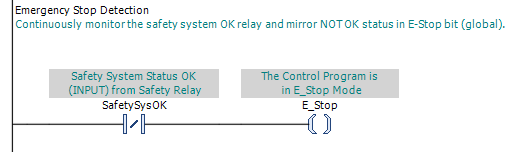
In a typical implementation, the invocation rung continuously monitors the safety-system status and writes the global "E-Stop" bit accordingly. The control program is in E-Stop Mode whenever the "E-Stop" bit is TRUE.
Implementation
The PLC Pro begins the implementation of E-Stop Mode by defining a globally scoped Boolean, commonly named "E-Stop," that represents whether the safety system is enforcing the Emergency Stop response. The control program is in E-Stop Mode whenever this bit is TRUE.
In most installations, loss of source power de-energizes the safety relay just as operation of an Emergency Stop device or another safety-system demand would. Because reset depends on power being available, restoration of all required safety-system conditions, and a deliberate reset command, it is normal to think of machines or installations as powering up in an Emergency Stop condition.
Many PLCs provide a built-in First Scan status bit or startup routine that executes once when program execution begins. The PLC Pro may use this capability to initialize the global "E-Stop" bit from the available safety-system status before normal machine operation is permitted.
If the PLC does not provide a built-in First Scan function, the PLC Pro can create an equivalent startup condition with a non-retained initialization bit that begins FALSE when the PLC powers up. While that bit is FALSE, the startup logic initializes the global "E-Stop" bit from the available safety-system status and then sets the initialization bit TRUE.
During normal operation, the control program continuously monitors the available safety-system status. This is commonly provided by a contact from the safety relay or status from a safety PLC. The global "E-Stop" bit must continuously mirror that status.
PLC Pro Design Rule
- The global "E-Stop" bit must continuously mirror the safety-system Emergency Stop status.